- AM335x Sitara™ Processors Datasheet
- AM335x Technical reference manual
- SN65HVD23x Datasheet
- PocketBeagle CAN0 overlay
- Guide about the EEPROM in BeagleBone Black
- How to start U-Boot console over UART
- Generate a Debian Image with U-Boot for BeagleBone Black
The DTUSAT OBC has a CAN bus for the interconnection of the different subsystems. It took me a lot of time to make it work, and this is the guide how I did it. The steps are:
- Configure the EEPROM of the OBC to be as a Pocket BeagleBone
- Fix some connections of the OBC
- Generate CAN overlay
- Apply the overlay
The configuration of the EEPROM is necessary to do it everytime a new OBC is used, because is written on the physical EEPROM.
Configure the EEPROM of the OBC to be as a Pocket BeagleBone
In the master thesis report of blanca is explaned how to boot linux for the first time, however there are some steps that were not done, that is the programming of the EEPROM. If the EEPROM is not programmed correctly the CPU is not capable to configure the drivers and the pinout. In order to configure the EEPROM is necessary to:
- Enable the EEPROM writting by connecting a jumper between the testpoint WP with GND.
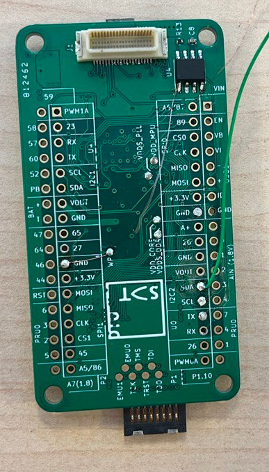
- Connect a UART interface, like a TTL to USB to the UART0 of the OBC. The UART0 is connected to the pin 2 and 4 of the 40 pin connector.
- Open a serial connection, 115200 baud, and power the OBC, when is booting you need to pause the startup and enter in the u-boot. And then enter the next information:
=> // Set i2c device
=> i2c dev 0
=>
=> // Set the header “magic number”:  0xAA5533EE
=> i2c mw 0x50 0x00.2 aa
=> i2c mw 0x50 0x01.2 55
=> i2c mw 0x50 0x02.2 33
=> i2c mw 0x50 0x03.2 ee
=>
=> // Set the Board name (bytes 0 – 4):  “A335”
=> i2c mw 0x50 0x04.2 41
=> i2c mw 0x50 0x05.2 33
=> i2c mw 0x50 0x06.2 33
=> i2c mw 0x50 0x07.2 35
=>
=> // Set the Board name (bytes 4 – 7):  “PBGL”
=> i2c mw 0x50 0x08.2 50
=> i2c mw 0x50 0x09.2 42
=> i2c mw 0x50 0x0a.2 47
=> i2c mw 0x50 0x0b.2 4C
=>
=> // Set the Board version - only required for BeagleBone devices.
=> i2c mw 0x50 0x0c.2 30
=> i2c mw 0x50 0x0d.2 30
=> i2c mw 0x50 0x0e.2 41
=> i2c mw 0x50 0x0f.2 32
=>
=> // Write the serial number, is not necessary, but just in case
=> i2c mw 0x50 0x10.2 31
=> i2c mw 0x50 0x11.2 37
=> i2c mw 0x50 0x12.2 35
=> i2c mw 0x50 0x13.2 30
=> i2c mw 0x50 0x14.2 45
=> i2c mw 0x50 0x15.2 50
=> i2c mw 0x50 0x16.2 42
=> i2c mw 0x50 0x17.2 30
=> i2c mw 0x50 0x18.2 36
=> i2c mw 0x50 0x19.2 38
=> i2c mw 0x50 0x1a.2 36
=> i2c mw 0x50 0x1b.2 32
-
Verify the content of the EEPROM by executing
i2c md 0x50 0x00.2 20.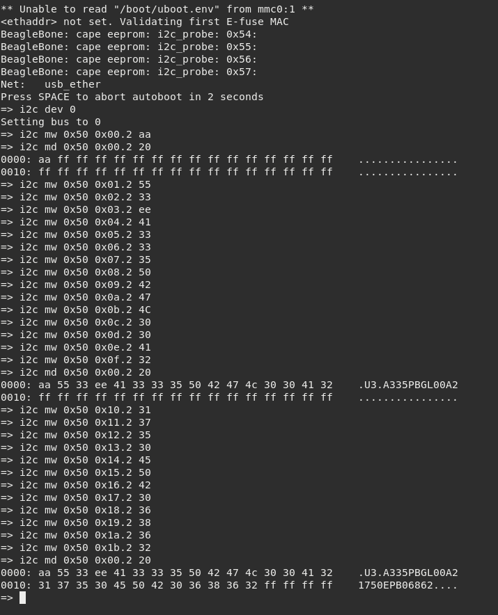
-
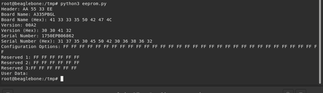
Remove the jumper and run the OBC as normal. When linux is running correctly check that the content of the EEPROM is correct by running the next python script, the output should be something like:
Fix some connections of the OBC
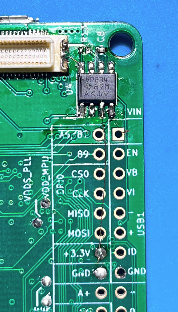
The OBC was designed to run with low power mode CAN, and the 3V3 to be ran by the SSCB. However on prototyping the OBC is not powered to a external 3V3, and also the CAN is connected to a high speed interface. It is necessary to make the next changes:
- Connect the Vcc (pin 3) of U4 to the +3.3V output of the OSD335x. This step is necessary when there is no 3.3V at the stack connector.
- Remove R13
- Connect Rs (pin 8) to GND, which could be the shield pin of the 40 pin connector. This way the component is running in high speed mode.
Generate CAN overlay
It is necessary to create an overlay to setup the pins, compile it, send it to the obc, and enable it on u-boot. The steps are:
- On your linux machine clone the repository of the overlays with
$ git clone https://github.com/beagleboard/bb.org-overlays.git. - Create the next files under
src/arm:
DTUSAT-CAN-0100.dts:
/*
 * Copyright (C) 2020 Robert Nelson <robertcnelson@gmail.com>
 *
 * This program is free software; you can redistribute it and/or modify
 * it under the terms of the GNU General Public License version 2 as
 * published by the Free Software Foundation.
 */

/dts-v1/;
/plugin/;

#include <dt-bindings/board/am335x-pb-base.h>
#include <dt-bindings/pinctrl/am33xx.h>

/ {
	/*
	 * Helper to show loaded overlays under: /proc/device-tree/chosen/overlays/
	 */
	fragment@0 {
		target-path="/";
		__overlay__ {

			chosen {
				overlays {
					DTUSAT-CAN-01A00 = __TIMESTAMP__;
				};
			};
		};
	};

  /*
	 * Free up the pins used by the cape from the pinmux helpers.
	 */
	fragment@1 {
		target = <&ocp>;
		__overlay__ {
            P1_28_pinmux { status = "disabled"; };	/* P1_28: i2c2_scl.d_can0_rx */
			P1_26_pinmux { status = "disabled"; };	/* P1_26: i2c2_sda.d_can0_tx */
		};
	};

	fragment@2 {
		target = <&am33xx_pinmux>;
		__overlay__ {

      /* DTUSAT CAN bus */
      DTUSAT_dcan0_pins: pinmux_dcan0_pins { pinctrl-single,pins = <
            AM33XX_IOPAD(0x0920, PIN_INPUT | MUX_MODE1)   /* MII1_TXD2.dcan0_rx */
		    AM33XX_IOPAD(0x091C, PIN_OUTPUT | MUX_MODE1) 	/* MII1_TXD3.dcan0_tx */
        >;
      };
		};
	};

	fragment@3 {
    target = <&dcan0>;
      __overlay__ {
        status = "okay";
        pinctrl-names = "default";
        pinctrl-0 = <&DTUSAT_dcan0_pins>;
    };
	};

};
DTUSAT-GPIO-03A00.dts:
/*
 * Copyright (C) 2020 Robert Nelson <robertcnelson@gmail.com>
 *
 * This program is free software; you can redistribute it and/or modify
 * it under the terms of the GNU General Public License version 2 as
 * published by the Free Software Foundation.
 */

/dts-v1/;
/plugin/;

#include <dt-bindings/gpio/gpio.h>
#include <dt-bindings/pinctrl/am33xx.h>

/ {
	/*
	 * Helper to show loaded overlays under: /proc/device-tree/chosen/overlays/
	 */
	fragment@0 {
		target-path="/";
		__overlay__ {

			chosen {
				overlays {
					DTUSAT-GPIO-03A00 = __TIMESTAMP__;
				};
			};
		};
	};

	fragment@1 {
		target = <&am33xx_pinmux>;
		__overlay__ {

      /* DTUSAT 40pin connector GPIO's and the CAN EN gpio */

      P11_default_pin: pinmux_P11_default_pin { pinctrl-single,pins = <
		    AM33XX_IOPAD(0x0948, PIN_OUTPUT | INPUT_EN | MUX_MODE7) /* (U1.E13)GPIO0_0: MDIO.gpio0_0 */
        >;
      };

      P13_default_pin: pinmux_P13_default_pin { pinctrl-single,pins = <
		    AM33XX_IOPAD(0x094C, PIN_OUTPUT | INPUT_EN | MUX_MODE7) /* (U1.D13)GPIO0_1: MDC.gpio0_1 */
        >;
      };

      P15_default_pin: pinmux_P15_default_pin { pinctrl-single,pins = <
		    AM33XX_IOPAD(0x0924, PIN_OUTPUT | INPUT_EN | MUX_MODE7) /* (U1.H14)GPIO0_21: MII1_TXD1.gpio0_21 */
        >;
      };

      P17_default_pin: pinmux_P17_default_pin { pinctrl-single,pins = <
		    AM33XX_IOPAD(0x0928, PIN_OUTPUT | INPUT_EN | MUX_MODE7) /* (U1.H15)GPIO0_28: MII1_TXD0.gpio0_28 */
        >;
      };

      P19_default_pin: pinmux_P19_default_pin { pinctrl-single,pins = <
		    AM33XX_IOPAD(0x0944, PIN_OUTPUT | INPUT_EN | MUX_MODE7) /* (U1.J14)GPIO0_29: RMII1_REF_CLK.gpio0_29 */
        >;
      };

      CAN_EN_default_pin: pinmux_CAN_EN_default_pin { pinctrl-single,pins = <
		    AM33XX_IOPAD(0x0914, PIN_OUTPUT | INPUT_EN | MUX_MODE7) /* (U1.G14)GPIO3_3: MII1_TX_EN.gpio3_3 */
        >;
      };
		};
	};

	fragment@2 {
		target=<&ocp>;
		__overlay__ {
      P11_pinmux {
        compatible = "bone-pinmux-helper";
        status = "okay";
        pinctrl-names = "default";
        pinctrl-0 = <&P11_default_pin>;
      };

      P13_pinmux {
        compatible = "bone-pinmux-helper";
        status = "okay";
        pinctrl-names = "default";
        pinctrl-0 = <&P13_default_pin>;
      };

      P15_pinmux {
        compatible = "bone-pinmux-helper";
        status = "okay";
        pinctrl-names = "default";
        pinctrl-0 = <&P15_default_pin>;
      };

      P17_pinmux {
        compatible = "bone-pinmux-helper";
        status = "okay";
        pinctrl-names = "default";
        pinctrl-0 = <&P17_default_pin>;
      };

      P19_pinmux {
        compatible = "bone-pinmux-helper";
        status = "okay";
        pinctrl-names = "default";
        pinctrl-0 = <&P19_default_pin>;
      };

      CAN_EN_pinmux {
        compatible = "bone-pinmux-helper";
        status = "okay";
        pinctrl-names = "default";
        pinctrl-0 = <&CAN_EN_default_pin>;
      };
		};
	};

  fragment@3 {
		target=<&ocp>;
		__overlay__ {
      cape-dtusat {
        compatible = "gpio-of-helper";
        status = "okay";
        pinctrl-names = "default";
        pinctrl-0 = <>;

        P11 {
          gpio-name = "P11";
          gpio = <&gpio0 0 0>;
          output;
          init-low;
        };

        P13 {
          gpio-name = "P13";
          gpio = <&gpio0 1 0>;
          output;
          init-low;
        };

        P15 {
          gpio-name = "P15";
          gpio = <&gpio0 21 0>;
          output;
          init-low;
        };

        P17 {
          gpio-name = "P17";
          gpio = <&gpio0 28 0>;
          output;
          init-low;
        };

        P19 {
          gpio-name = "P19";
          gpio = <&gpio0 29 0>;
          output;
          init-low;
        };

        CAN_EN {
          gpio-name = "CAN_EN";
          gpio = <&gpio3 3 0>;
          output;
              init-high;    //Enable CAN on startup
        };
      };
		};
	};
};
- Compile it by going to the root folder of the repository and running
$ make - Copy the compiled overlays (with extension .dtbo) in
/lib/firmwarein the OBC. - Modify the content of
/boot/uEnv.txtand add the overlays like:
uboot_overlay_addr0=/lib/firmware/DTUSAT-CAN-0100.dts.dtbo
uboot_overlay_addr1=/lib/firmware/DTUSAT-GPIO-03A00.dts.dtbo
- Reboot
Apply the overlay
In the OBC we need to enable the can interface by:
$ echo 1 > /sys/class/gpio/gpio99/value # enable the CAN transceiver
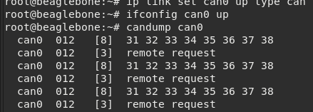
$ sudo ip link set can0 up type can bitrate 500000
$ sudo ifconfig can0 up
$ cansend can0 5A1#00.01.02.03.04
For this example I connected an arduino with a CAN transceiver transmitting some packets, 20230418 - ESP32 and CAN transceiver, and I am able to receive with:
Create CAN interface on startup
In order to configure everything from startup you need to add the following lines to /etc/systemd/system/can_enable.service:
[Unit]
Description=Setup SocketCAN interface can0 with a baudrate of 500000
After=multi-user.target

[Service]
Type=oneshot
RemainAfterExit=yes
ExecStartPre=/sbin/ip link set can0 up type can bitrate 500000
ExecStart=/sbin/ifconfig can0 up
ExecStop=/sbin/ifconfig can0 down

[Install]
WantedBy=multi-user.target
and then:
# systemclt daemon-reload
# systemctl start can_enable.service
# systemctl enable can_enable.service