I wrote a guide about how to implement the CAN interface in the OBC:
How to connect
- Boot the PCB with the USB cable
- Selec the correct network card, as DHCP
- Connect through SSH as
ssh debian@192.168.7.2 -p 22- User: debian
- Pass: temppwd
Update 28 Feb 2023
SSH Connection:
- User: debian
- Pass: temppwd
Status of the PCB:
- The OBC of Blanca boots up, and behave as expected. I guess the PCB is correct and it behaves similar to the original beaglebone pocketbeagle. It is working perfectly.
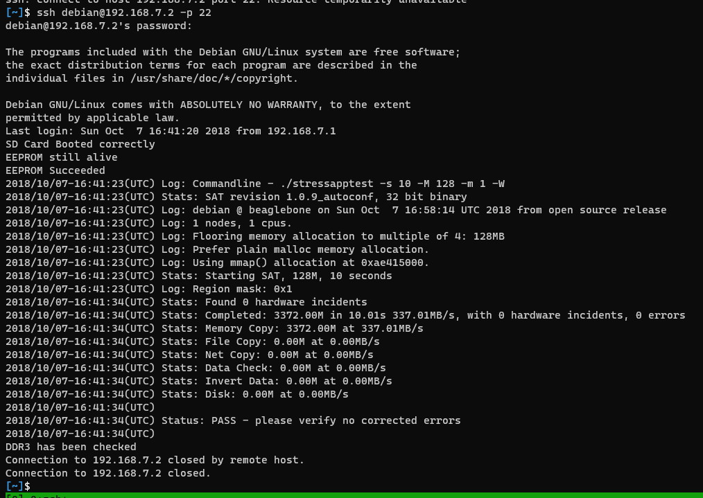
When connected through ssh it runs a stressapp that hangs the board. I fixed it by comenting the profile script at /etc/profile.
With this guide you can enable internet access on windows computer. It didnt work on linux computer >.<
Update 21 April
The octavio SOC is a set of chip in the same package. The CAN bus is connected directly to the controller inside the microcontroller, to check the pinout, you need to check the connections with the microcontroller.
The only reason I find why is G15, G16 is because is in the SIP D and the datasheet state D15 and D16.
To listen CAN candump can0.
Some questions:
- Why blanca chose those pins?
- No idea
- Is the pocketbeagle connecting the CAN bus.
Pockebeagle pinout?
- Yes, the pocketbeagle is connecting the both interfaces in the P1 and P2
- Why the interface is not created on startup or run overlays?
- It is necessary to run the firmware library. in vim /boot/uEnv.txt
- Is the pin configured on the OBC for CAN?
- It seems that is configured for the pins of beagle, but not the new pins. I need to know how to change them.
- The firmware library is under https://github.com/beagleboard/bb.org-overlays/tree/master/src/arm and can be compiled to be added using this guide https://bootlin.com/blog/using-device-tree-overlays-example-on-beaglebone-boards/
In order to change the pin location:
-
In the beaglebone black the pin locations have the next address https://github.com/derekmolloy/boneDeviceTree/blob/master/docs/BeagleboneBlackP8HeaderTable.pdf, that is imported in the next file https://github.com/beagleboard/bb.org-overlays/blob/1b5a2241bff95111dd02dece1d7b13f603a708f5/include/dt-bindings/board/am335x-bbw-bbb-base.h I am not understanding where the addresses are set. In this readme it is explained how it works the pin selection in beagle bone https://github.com/cdsteinkuehler/beaglebone-universal-io
How to look up pins
- Go to page 11, the name in each cell is the one used in the symbol in the shematics of Blanca. From that cell you can get the column and number, as A18. and then on the table 4.2 you can check the uses of that pin.
In the case of Beaglebone pocket:
- CAN0 TX is on UART1_CTSN, E17 D18
- Then in the overlay it is listed the MUX mode, from the table of the datasheet they give you the mode.
- This file describe the number of the pocketbeagle with the board connection. However, the can overlay uses the beaglebone black pin.
- In this file you can get the address of the pins of the microcontroller https://github.com/beagleboard/bb.org-overlays/blob/1b5a2241bff95111dd02dece1d7b13f603a708f5/include/dt-bindings/pinctrl/am33xx.h
- The address and the offset can be found in the technical reference manual in page 180 it said that the control module register is on 0x44E1_0000, and the list of offset is on page 1461.
Finally, I found how to do it. PinMux for OSD335x Family and AM335x SoC
CUSTOM OVERLAY TO ENABLE CAN BUS
/*
 * Copyright (C) 2015 Robert Nelson <robertcnelson@gmail.com>
 *
 * Virtual cape for CAN0 on connector pins for P1.28 and P1.26 on PocketBeagle
 *
 * This program is free software; you can redistribute it and/or modify
 * it under the terms of the GNU General Public License version 2 as
 * published by the Free Software Foundation.
 */
/dts-v1/;
/plugin/;

#include <dt-bindings/pinctrl/am33xx.h>
#include <dt-bindings/board/am335x-pb-base.h>

/ {
	/*
	 * Helper to show loaded overlays under: /proc/device-tree/chosen/overlays/
	 */
	fragment@0 {
		target-path="/";
		__overlay__ {

			chosen {
				overlays {
					DTUSAT-CAN0-00A0 = __TIMESTAMP__;
				};
			};
		};
	};

	fragment@1 {
		target = <&am33xx_pinmux>;
		__overlay__ {
			dtusat_dcan0_pins: pinmux_dcan0_pins {
				/* https://github.com/beagleboard/BeagleBoard-DeviceTrees/blob/v4.19.x-ti/src/arm/am335x-pocketbeagle.dts#L320 */
                /* MODIFIED */
				pinctrl-single,pins = <
					AM33XX_IOPAD(AM335X_PIN_MII1_TXD2, PIN_INPUT_PULLUP | MUX_MODE1)          /* uart1_rtsn.dcan0_rx */
					AM33XX_IOPAD(AM335X_PIN_MII1_TXD3, PIN_OUTPUT_PULLUP | MUX_MODE1)         /* uart1_ctsn.dcan0_tx */
				>;
			};
		};
	};

	fragment@2 {
		target = <&dcan0>;
		__overlay__ {
			status = "okay";
			pinctrl-names = "default";
			pinctrl-0 = <&dtusat_dcan0_pins>;
		};
	};
};
One of the reasons I was confusing all the time was that I was looking for beaglebone black, when it should be pocket beagle.
Update 20 Apr 2023
I am starting to implement the CAN bus to interconnect the OBC with a simple ESP32. I removed the load capacitor becuase it seems that they are not necessary, they board works fine without the resistors.
How to setup the P11 of the 40 pin as led
-
OSD335x Lesson 2: Linux Device Tree The Device tree of the octavo is given by the manufacturer, it is a complex file describin all the peripherals of the system.
You can see what overlays are loaded with ls /proc/device-tree/chosen/overlays/. By default the only overlay that is loaded is AM335X-PRU-RPROC-4-14-TI-00A0,
source.
How to flash a led. You can power some leds by going to cd /sys/class/leds, go to any led and then echo 1 > brightness. Also it is possible to access the GPIO by going to cd /sys/class/gpio, and write to export with “The gpio pins are in banks of 32 each, for the GPIO_1_28 it is 1*32+28=60”, then echo 60 > exportandecho 1 > value.
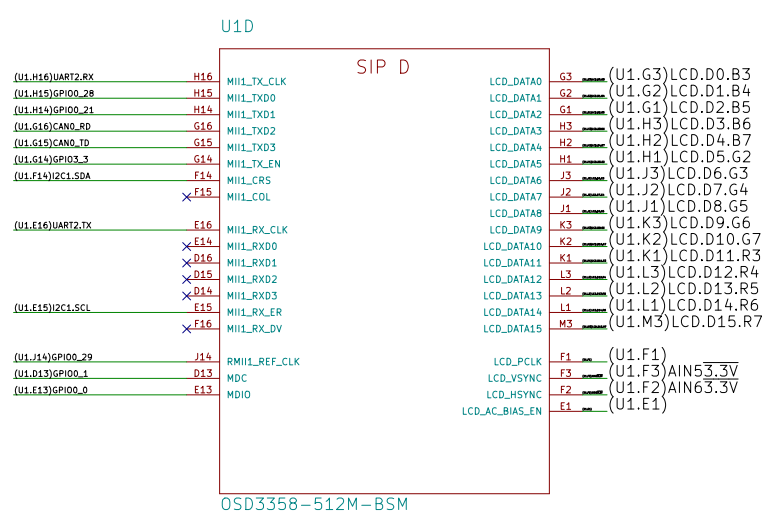
The 40 pin connector connections with the Octavo are the next. The first is the name in the 40 pin connector, the second is the name in the octavo (the same as in AM335) (page 39 of datahseet of am335), and the third is the control module register (page 1458 of technical reference):
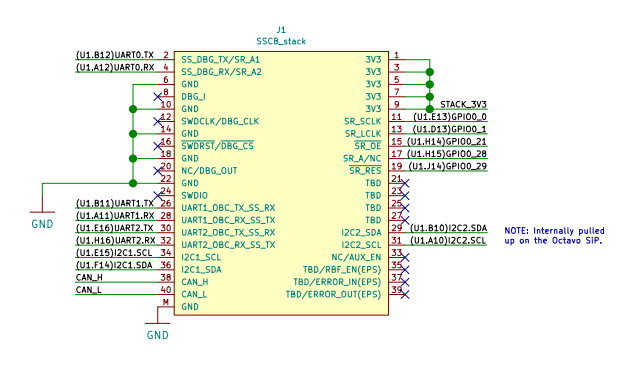
(U1.B12)UART0.TX-> P1.30 of the beagle header and UART0_TXD (OSD335)(U1.A12)UART0.RX-> P1.32 of the beagle header and UART0_RXD (OSD335)(U1.B11)UART1.TX-> UART1_TXD (OSD335)(U1.A11)UART1.RX-> UART1_RXD (OSD335)(U1.E16)UART2.TX-> MII1_RX_CLK (OSD335)(U1.H16)UART2.RX-> MII1_TX_CLK (OSD335)(U1.E15)I2C1.SCL-> MII1_CRS (OSD335)(U1.F14)I2C1.SDA-> MII1_CRS (OSD335)(U1.E13)GPIO0_0(P11) -> MDIO (OSD335) -> 948h conf_mdio(U1.D13)GPIO0_1(P13) -> MDC (OSD335) -> 94Ch conf_mdc(U1.H14)GPIO0_21(P15) -> MII1_TXD1 (OSD335) -> 924h conf_mii1_txd1(U1.H15)GPIO0_28(P17) -> MII1_TXD0 (OSD335) -> 928h conf_mii1_txd0(U1.J14)GPIO0_29(P19) -> RMII1_REF_CLK(OSD335) -> 944h conf_rmii1_ref_clk(U1.B10)I2C2.SDA-> P1.26 of the beagle header and UART1_CTSN (OSD335)(U1.A10)I2C2.SCL-> P1.28 of the beagle header and UART1_RTSN (OSD335)
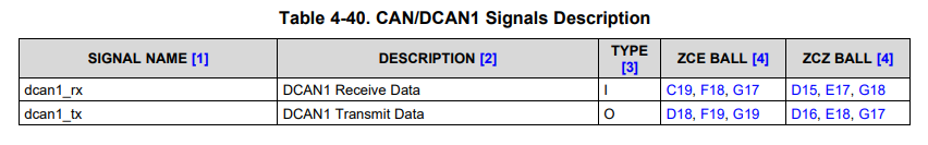
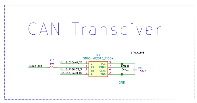
The pins used for the CAN transceiver:
(U1.G15)CAN0_TD-> MII1_TXD3 (OSD335) -> 91Ch(U1.G16)CAN0_RD-> qq (OSD335) -> 920h(U1.G14)GPIO3_3-> MII1_TX_EN (OSD335) -> 914h
Then go to page 1458 of the technical reference manual.
The steps are:
- On a linux machine do:
$ sudo apt-get install device-tree-compiler
$ sudo apt install gcc-arm-linux-gnueabihf
$ git clone https://github.com/beagleboard/bb.org-overlays.git
Copy your dts file at src/arm and then on the root folder do make. Paste the dtbo in the folder /lib/firmware at the beagle. Then modify the /boot/uEnv.txt and add the overlay. Reset.
Check that your overlay is working with ls /proc/device-tree/chosen/overlays.
You can test the led with cd /sys/class/leds and then echo 1 > brightness
The code to make the GPIO_0_0 a led:
/*
 * Copyright (C) 2020 Robert Nelson <robertcnelson@gmail.com>
 *
 * This program is free software; you can redistribute it and/or modify
 * it under the terms of the GNU General Public License version 2 as
 * published by the Free Software Foundation.
 */

/dts-v1/;
/plugin/;

#include <dt-bindings/gpio/gpio.h>
#include <dt-bindings/pinctrl/am33xx.h>

/ {
	/*
	 * Helper to show loaded overlays under: /proc/device-tree/chosen/overlays/
	 */
	fragment@0 {
		target-path="/";
		__overlay__ {

			chosen {
				overlays {
					DTUSAT-LED-01A00 = __TIMESTAMP__;
				};
			};
		};
	};

	fragment@1 {
		target = <&am33xx_pinmux>;
		__overlay__ {

      /* DTUSAT P11 in 40pin connector (U1.E13)GPIO0_0: MDIO.gpio0_0 */
      P11_default_pin: pinmux_P11_default_pin { pinctrl-single,pins = <
        AM33XX_PADCONF(0x0948, PIN_OUTPUT, MUX_MODE7) >; };	/* (U1.E13)GPIO0_0: MDIO.gpio0_0 */
		};
	};

	fragment@2 {
		target-path="/";
		__overlay__ {

			leds {
				pinctrl-names = "default";
				pinctrl-0 = <&P11_default_pin>;

				compatible = "gpio-leds";

				P11 {
					label = "P11";
					gpios = <&gpio0 0 GPIO_ACTIVE_HIGH>;
					default-state = "off";
				};
			};
		};
	};
};
How to setup P11 of the 40pin connector as gpio
/*
 * Copyright (C) 2020 Robert Nelson <robertcnelson@gmail.com>
 *
 * This program is free software; you can redistribute it and/or modify
 * it under the terms of the GNU General Public License version 2 as
 * published by the Free Software Foundation.
 */

/dts-v1/;
/plugin/;

#include <dt-bindings/gpio/gpio.h>
#include <dt-bindings/pinctrl/am33xx.h>

/ {
	/*
	 * Helper to show loaded overlays under: /proc/device-tree/chosen/overlays/
	 */
	fragment@0 {
		target-path="/";
		__overlay__ {

			chosen {
				overlays {
					DTUSAT-GPIO-02A00 = __TIMESTAMP__;
				};
			};
		};
	};

	fragment@1 {
		target = <&am33xx_pinmux>;
		__overlay__ {

      /* DTUSAT P11 in 40pin connector (U1.E13)GPIO0_0: MDIO.gpio0_0 */
      P11_default_pin: pinmux_P11_default_pin { pinctrl-single,pins = <
		    AM33XX_IOPAD(0x0948, PIN_OUTPUT | INPUT_EN | MUX_MODE7) >; };	/* MDIO.gpio0_0 */
		};
	};

	fragment@2 {
		target=<&ocp>;
		__overlay__ {
      P11_pinmux {
        compatible = "bone-pinmux-helper";
        status = "okay";
        pinctrl-names = "default";
        pinctrl-0 = <&P11_default_pin>;
      };
		};
	};

  fragment@3 {
		target=<&ocp>;
		__overlay__ {
      cape-dtusat {
        compatible = "gpio-of-helper";
        status = "okay";
        pinctrl-names = "default";
        pinctrl-0 = <>;

        P11 {
          gpio-name = "P11";
          gpio = <&gpio0 0 0>;
          output;
          init-low;
        };
      };
		};
	};
};
And to test it, you can check that the overlay is in place in /proc/device-tree/ocp under P11. You can control de GPIO in /sys/class/gpio/gpio0, by echo 1 > value.
DTUSAT GPIOs in the 40 pin and CAN EN setup
/*
 * Copyright (C) 2020 Robert Nelson <robertcnelson@gmail.com>
 *
 * This program is free software; you can redistribute it and/or modify
 * it under the terms of the GNU General Public License version 2 as
 * published by the Free Software Foundation.
 */

/dts-v1/;
/plugin/;

#include <dt-bindings/gpio/gpio.h>
#include <dt-bindings/pinctrl/am33xx.h>

/ {
	/*
	 * Helper to show loaded overlays under: /proc/device-tree/chosen/overlays/
	 */
	fragment@0 {
		target-path="/";
		__overlay__ {

			chosen {
				overlays {
					DTUSAT-GPIO-03A00 = __TIMESTAMP__;
				};
			};
		};
	};

	fragment@1 {
		target = <&am33xx_pinmux>;
		__overlay__ {

      /* DTUSAT 40pin connector GPIO's and the CAN EN gpio */

      P11_default_pin: pinmux_P11_default_pin { pinctrl-single,pins = <
		    AM33XX_IOPAD(0x0948, PIN_OUTPUT | INPUT_EN | MUX_MODE7) /* (U1.E13)GPIO0_0: MDIO.gpio0_0 */
        >;
      };

      P13_default_pin: pinmux_P13_default_pin { pinctrl-single,pins = <
		    AM33XX_IOPAD(0x094C, PIN_OUTPUT | INPUT_EN | MUX_MODE7) /* (U1.D13)GPIO0_1: MDC.gpio0_1 */
        >;
      };

      P15_default_pin: pinmux_P15_default_pin { pinctrl-single,pins = <
		    AM33XX_IOPAD(0x0924, PIN_OUTPUT | INPUT_EN | MUX_MODE7) /* (U1.H14)GPIO0_21: MII1_TXD1.gpio0_21 */
        >;
      };

      P17_default_pin: pinmux_P17_default_pin { pinctrl-single,pins = <
		    AM33XX_IOPAD(0x0928, PIN_OUTPUT | INPUT_EN | MUX_MODE7) /* (U1.H15)GPIO0_28: MII1_TXD0.gpio0_28 */
        >;
      };

      P19_default_pin: pinmux_P19_default_pin { pinctrl-single,pins = <
		    AM33XX_IOPAD(0x0944, PIN_OUTPUT | INPUT_EN | MUX_MODE7) /* (U1.J14)GPIO0_29: RMII1_REF_CLK.gpio0_29 */
        >;
      };

      CAN_EN_default_pin: pinmux_CAN_EN_default_pin { pinctrl-single,pins = <
		    AM33XX_IOPAD(0x0914, PIN_OUTPUT | INPUT_EN | MUX_MODE7) /* (U1.G14)GPIO3_3: MII1_TX_EN.gpio3_3 */
        >;
      };
		};
	};

	fragment@2 {
		target=<&ocp>;
		__overlay__ {
      P11_pinmux {
        compatible = "bone-pinmux-helper";
        status = "okay";
        pinctrl-names = "default";
        pinctrl-0 = <&P11_default_pin>;
      };

      P13_pinmux {
        compatible = "bone-pinmux-helper";
        status = "okay";
        pinctrl-names = "default";
        pinctrl-0 = <&P13_default_pin>;
      };

      P15_pinmux {
        compatible = "bone-pinmux-helper";
        status = "okay";
        pinctrl-names = "default";
        pinctrl-0 = <&P15_default_pin>;
      };

      P17_pinmux {
        compatible = "bone-pinmux-helper";
        status = "okay";
        pinctrl-names = "default";
        pinctrl-0 = <&P17_default_pin>;
      };

      P19_pinmux {
        compatible = "bone-pinmux-helper";
        status = "okay";
        pinctrl-names = "default";
        pinctrl-0 = <&P19_default_pin>;
      };

      CAN_EN_pinmux {
        compatible = "bone-pinmux-helper";
        status = "okay";
        pinctrl-names = "default";
        pinctrl-0 = <&CAN_EN_default_pin>;
      };
		};
	};

  fragment@3 {
		target=<&ocp>;
		__overlay__ {
      cape-dtusat {
        compatible = "gpio-of-helper";
        status = "okay";
        pinctrl-names = "default";
        pinctrl-0 = <>;

        P11 {
          gpio-name = "P11";
          gpio = <&gpio0 0 0>;
          output;
          init-low;
        };

        P13 {
          gpio-name = "P13";
          gpio = <&gpio0 1 0>;
          output;
          init-low;
        };

        P15 {
          gpio-name = "P15";
          gpio = <&gpio0 21 0>;
          output;
          init-low;
        };

        P17 {
          gpio-name = "P17";
          gpio = <&gpio0 28 0>;
          output;
          init-low;
        };

        P19 {
          gpio-name = "P19";
          gpio = <&gpio0 29 0>;
          output;
          init-low;
        };

        CAN_EN {
          gpio-name = "CAN_EN";
          gpio = <&gpio3 3 0>;
          output;
          init-low;
        };
      };
		};
	};
};
DTUSAT CAN Bus
/*
 * Copyright (C) 2020 Robert Nelson <robertcnelson@gmail.com>
 *
 * This program is free software; you can redistribute it and/or modify
 * it under the terms of the GNU General Public License version 2 as
 * published by the Free Software Foundation.
 */

/dts-v1/;
/plugin/;

#include <dt-bindings/gpio/gpio.h>
#include <dt-bindings/pinctrl/am33xx.h>

/ {
	/*
	 * Helper to show loaded overlays under: /proc/device-tree/chosen/overlays/
	 */
	fragment@0 {
		target-path="/";
		__overlay__ {

			chosen {
				overlays {
					DTUSAT-CAN-01A00 = __TIMESTAMP__;
				};
			};
		};
	};

	fragment@1 {
		target = <&am33xx_pinmux>;
		__overlay__ {

      /* DTUSAT CAN bus */
      DTUSAT_dcan0_pins: pinmux_DTUSAT_dcan0_pins { pinctrl-single,pins = <
		    AM33XX_IOPAD(0x091C, PIN_OUTPUT_PULLUP | MUX_MODE1) 	/* MII1_TXD3.dcan0_tx */
        AM33XX_IOPAD(0x0920, PIN_INPUT_PULLUP | MUX_MODE1)   /* MII1_TXD2.dcan0_rx */
        >;
      };
		};
	};

	fragment@2 {
    target = <&dcan0>;
      __overlay__ {
        status = "okay";
        pinctrl-names = "default";
        pinctrl-0 = <&DTUSAT_dcan0_pins>;
    };
	};

};
echo 1 > /sys/class/gpio/gpio99/value
sudo ip link set can0 up type can bitrate 500000
sudo ifconfig can0 up
cansend can0 5A1#00.01.02.03.04
Pocket beagle CAN
I did a test and is working:
- Connect the CAN0 bus on pocket beagle to the can transceiver I use in esp32
- Apply overlay of pocketbeagle
- Put esp32 in receiver mode
- configure can bus on beagle and cansend a dummy packet.
- I was able to receive it
The same test but with the esp32 as sender is working
Note: In the uBoot needs to be the universal cape.
It is working in the pocket beagle but not on the dtusat pcb. What I am doing is conecting directly to the port and see with the osciloscopio. dmesg output:
[    0.899646] CAN device driver interface
[    0.901517] c_can_platform 481cc000.can: c_can_platform device registered (regs=fa1cc000, irq=39)
[    0.902778] c_can_platform 481d0000.can: c_can_platform device registered (regs=fa1d0000, irq=40)
[    0.971745] can: controller area network core (rev 20170425 abi 9)
[   45.857412] c_can_platform 481cc000.can can0: setting BTR=1c02 BRPE=0000
[   45.863747] IPv6: ADDRCONF(NETDEV_CHANGE): can0: link becomes ready
[   62.826685] can: raw protocol (rev 20170425)
[   62.829497] c_can_platform 481cc000.can can0: bus-off
When I run my can overlay without the gpio I get the next:
[    1.137361] c_can_platform 481cc000.can: c_can_platform device registered (regs=fa1cc000, irq=37)
[    1.138768] pinctrl-single 44e10800.pinmux: pin PIN71 already requested by 481cc000.can; cannot claim for 4a100000.ethernet
[    1.150116] pinctrl-single 44e10800.pinmux: pin-71 (4a100000.ethernet) status -22
[    1.157694] pinctrl-single 44e10800.pinmux: could not request pin 71 (PIN71) from group cpsw_default  on device pinctrl-single
[    1.169188] cpsw 4a100000.ethernet: Error applying setting, reverse things back
And is not sending data like in the example of the pocketbeagle., that is conflicting with the
base overlay (not sure). But is coflicting with /proc/device-tree/ocp -->/ethernet@4a100000.
cat clock-names fckroo
cat clocks 6
cat compatible ti,am3352-d_can
cat interrupts 4
clock-names clocks compatible interrupts name phandle pinctrl-0 pinctrl-names reg status syscon-raminit ti,hwmods
When I remove all the overlays the can bus is already configured, I should check that.
In /sys/kernel/debug/pinctrl/44e10800.pinmux/pinmux-pins is possible to see the pins that are configured. Also in /sys/kernel/debug/pinctrl/pinctrl-maps
pin 71 (PIN71): 481cc000.can (GPIO UNCLAIMED) function pinmux_DTUSAT_dcan0_pins group pinmux_DTUSAT_dcan0_pins pin 72 (PIN72): 481cc000.can (GPIO UNCLAIMED) function pinmux_DTUSAT_dcan0_pins group pinmux_DTUSAT_dcan0_pins
With the pb configuration:
In pinctrl-maps:
device ocp:P9_19_pinmux
state can
type MUX_GROUP (2)
controlling device 44e10800.pinmux
group pinmux_P9_19_can_pin
function pinmux_P9_19_can_pin

device ocp:P9_20_pinmux
state can
type MUX_GROUP (2)
controlling device 44e10800.pinmux
group pinmux_P9_20_can_pin
function pinmux_P9_20_can_pin


device 481cc000.can
state default
type MUX_GROUP (2)
controlling device 44e10800.pinmux
group pinmux_dcan0_pins
function pinmux_dcan0_pins
In pinmux-pins:
pin 94 (PIN94): 481cc000.can (GPIO UNCLAIMED) function pinmux_dcan0_pins group pinmux_dcan0_pins
pin 95 (PIN95): 481cc000.can (GPIO UNCLAIMED) function pinmux_dcan0_pins group pinmux_dcan0_pins
UPDATE I connected to the CAN bus directly, the same in the PB and the DTUSAT and the device tree have different response: output of dtusat
[    1.135551] CAN device driver interface
[    1.135965] pinctrl-single 44e10800.pinmux: pin PIN95 already requested by ocp:P9_19_pinmux; cannot claim for 481cc000.can
[    1.147176] pinctrl-single 44e10800.pinmux: pin-95 (481cc000.can) status -22
[    1.154316] pinctrl-single 44e10800.pinmux: could not request pin 95 (PIN95) from group pinmux_dcan0_pins  on device pinctrl-single
[    1.166245] c_can_platform 481cc000.can: Error applying setting, reverse things back
[    1.174104] c_can_platform: probe of 481cc000.can failed with error -22
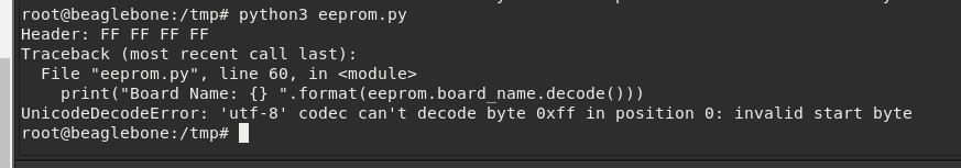
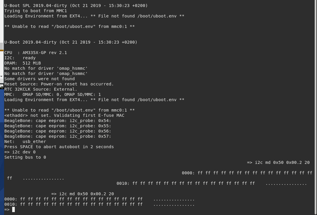
The error why I am not able to run can on the dtusat is because there might be something missing in the Eeprom related to the peripherals. The only reason for this is that the EEPROM in the pocketbeagle and the OBC are different, so I am going to create my own image and access the EEPROM.
EDIT 20230505:
- However after modifying the content of the eeprom with the values of the pocketbeagle, I am able to reproduce the same example as the beginning of this section using the same pin as in the pb but in the dtusat. But when I try with the new pins, nothing is sended.
- I desoldered the can transceiver, and the overlay seems to work perfectly.
- I discovered that is necessary to connect the 3v3 of the 40pin connector to 3v3 because there is no internal regulator. After that, and modifying the overlay I AM ABLE TO SEND DATA TO THE TRANSCEIVER, I tested that by connecting the input of the transceiver to the osciloscope and sending a dummy packet.
- FINALLY I AM ABLE TO RECEIVE PACKETS! By setting the mode to high speed. AND ALSO TO SEND PACKETS, IT IS WORKING!!!!
20230505 Accessing the EEPROM
Using this repo on the pocket beagle:
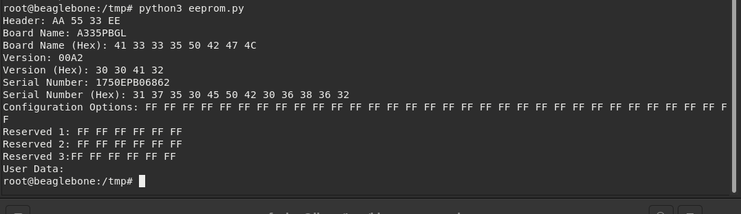
And on the OBC:
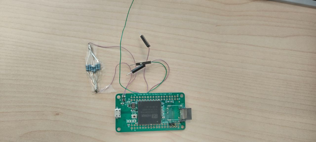
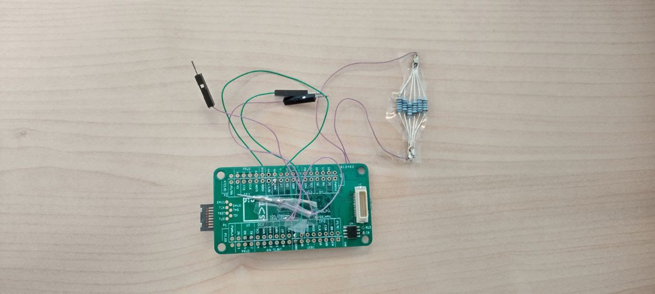
It is necessary to access the uBoot. To do that is necessary to connect to the UART interface. In UART0_TXD and UART0_RXD. Connecting with a normal TTL to usb with si on the pocketbeagle:
On the DTUSAT OBC, the UART0 interface is in the 40 pin connector, pin 2(TX) and 4(RX). The output in the DTUSAT OBC:
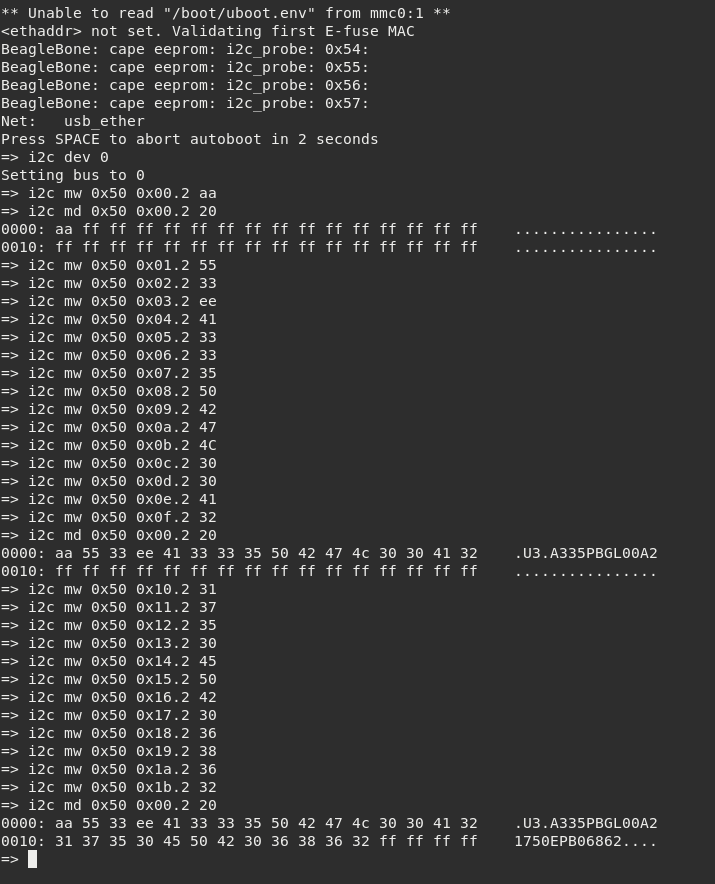
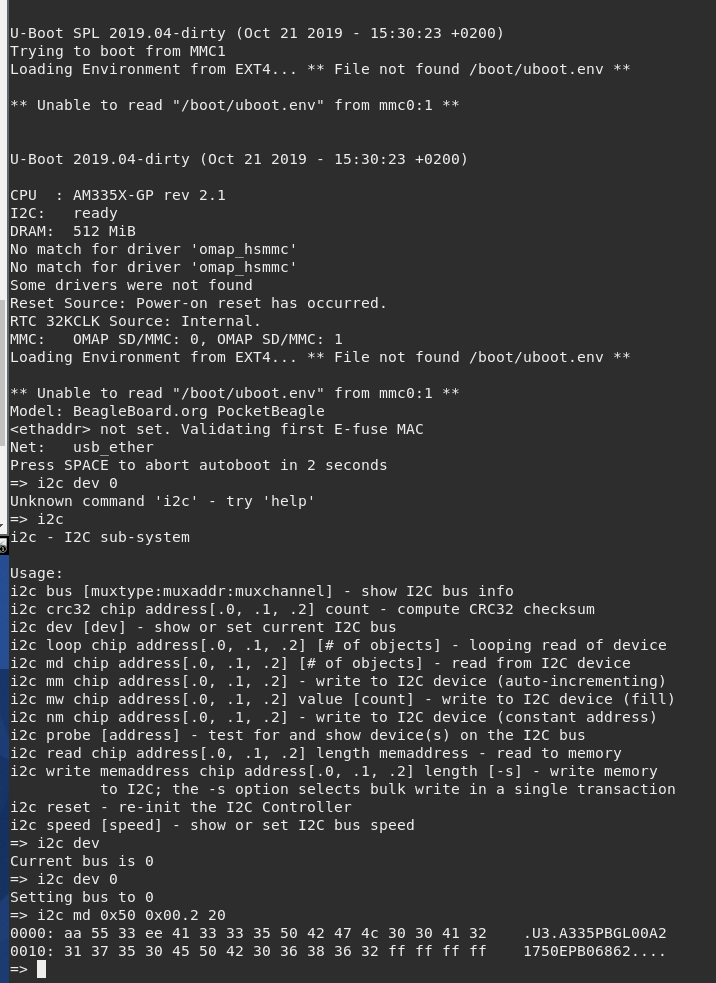
We can see that the eeprom is not programmed, we need to run:
=> // Set i2c device
=> i2c dev 0
=>
=> // Set the header “magic number”:  0xAA5533EE
=> i2c mw 0x50 0x00.2 aa
=> i2c mw 0x50 0x01.2 55
=> i2c mw 0x50 0x02.2 33
=> i2c mw 0x50 0x03.2 ee
=>
=> // Set the Board name (bytes 0 – 4):  “A335”
=> i2c mw 0x50 0x04.2 41
=> i2c mw 0x50 0x05.2 33
=> i2c mw 0x50 0x06.2 33
=> i2c mw 0x50 0x07.2 35
=>
=> // Set the Board name (bytes 4 – 7):  “PBGL”
=> i2c mw 0x50 0x08.2 50
=> i2c mw 0x50 0x09.2 42
=> i2c mw 0x50 0x0a.2 47
=> i2c mw 0x50 0x0b.2 4C
=>
=> // Set the Board version - only required for BeagleBone devices.
=> i2c mw 0x50 0x0c.2 30
=> i2c mw 0x50 0x0d.2 30
=> i2c mw 0x50 0x0e.2 41
=> i2c mw 0x50 0x0f.2 32
=>
=> // Write the serial number, is not necessary, but just in case
=> i2c mw 0x50 0x10.2 31
=> i2c mw 0x50 0x11.2 37
=> i2c mw 0x50 0x12.2 35
=> i2c mw 0x50 0x13.2 30
=> i2c mw 0x50 0x14.2 45
=> i2c mw 0x50 0x15.2 50
=> i2c mw 0x50 0x16.2 42
=> i2c mw 0x50 0x17.2 30
=> i2c mw 0x50 0x18.2 36
=> i2c mw 0x50 0x19.2 38
=> i2c mw 0x50 0x1a.2 36
=> i2c mw 0x50 0x1b.2 32
I have tried to write on the eeprom, but it is not working for some reason:
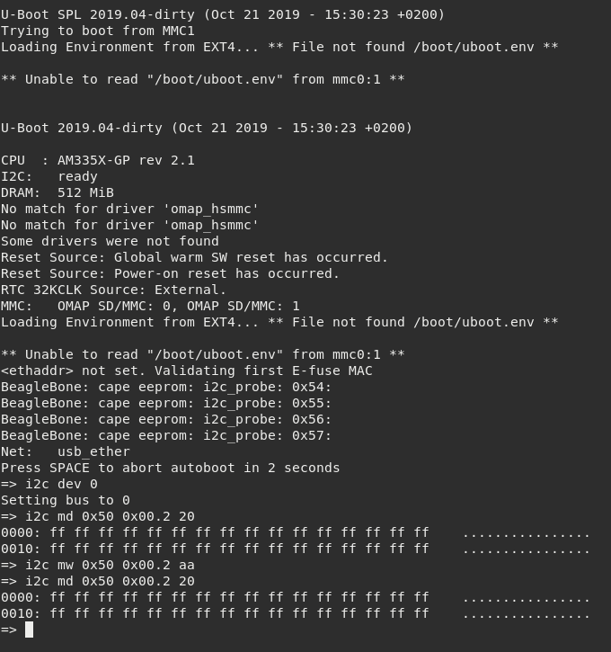
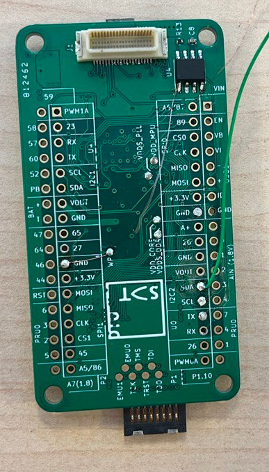
It seems that you need to ground the EEPROM_WP to edit the eeprom, that is (U1.M2)EEPROM.WP, that on the DTUSAT OBC is in the TP WP, needs to be grounded like:
After connecting that I was able to modify the eeprom and put it exactly as in the pocketbeagle: