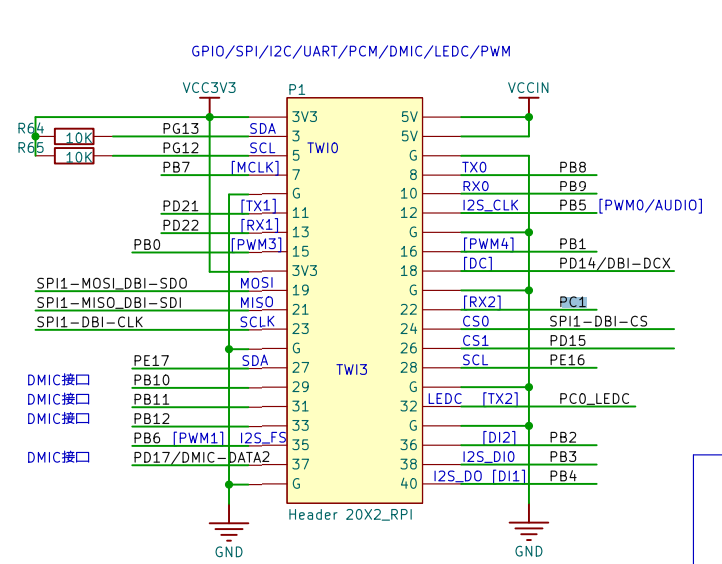
- Schematics of the MangoPi
- Repo of examples overlays
- The interrupt signal is connected to the Allwinner D1.
- The original overlay that is being executed.
- Guide to add CAN controller on Raspberry pi zero
- People adding the CAN Controller on OrangePi
The process to enable the external CAN controller is similar to the one I did with the Beaglebone. 20230505 - DTUSAT OBC Enabling CAN Bus.
I still need to understand some things of the overlay.
Wiring
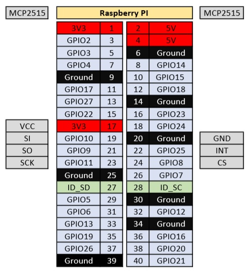
The SI, SO, SCK, CS are connected to the SPI1 of the Allwinner D1. The interrupt is connected to PC1/UART2-RX/TWI2-SDA/PC-EINT1.
Multiplex / Pin selection
Some information I can get from the document:
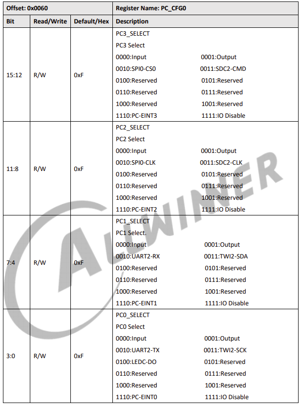
- PC1 functions are described in table 9-22 PC Multiplex Function, page 1086
- PC1_SELECT register description. Page 1104:
The information of the SPI is under /sys/class/gpio/gpiochip0/device/driver/2000000.pinctrl/consumer:platform:4025000.spi, and also here /sys/class/spi_master/spi0/device/supplier:platform:2000000.pinctrl.
Debug some important files to make this work
A bit of reverse engineering from 20230808 - CAN on Raspberry zero - debug
Overlay
/dts-v1/;
/plugin/;

/ {
	compatible = "allwinner,d1-nezha\0allwinner,sun20i-d1";

	fragment@0 {
		target-path = "/clocks";
		__overlay__ {
			#address-cells = <1>;
			#size-cells = <1>;
            /* External crystal oscillator on the board */
			can0_osc_fixed: can0_osc_fixed {
				compatible = "fixed-clock";
                #clock-cells = <0>;
                clock-frequency  = <8000000>;
                phandle = <0x81>;
			};
		};
	};

	fragment@1 {
		target = <&pinctrl>; // pinctrl@2000000
		__overlay__ {
			can0_pin_irq: can0_pin_irq {
				pins = "PD17";
                function = "irq";
                phandle = <0x85>;
			};
		};
	};

	fragment@2 {
		target = <&spi>;   //spi@4026000
		__overlay__ {
			#address-cells = <1>;
			#size-cells = <0>;
			status = "okay";
			mcp2515 {
				reg = <0>;		// SPI 1
                compatible = "microchip,mcp2515";
                pinctrl-names = "default";
                pinctrl-0 = <0x85>;
                spi-max-frequency = <10000000>;
                interrupt-parent = <0x22>; // pinctrl@2000000
                interrupts = <0 113 2>; // IRQ LINE, try with <0 65 2>
                clocks = <0x81>;
                status = "okay";
			};
		};
	};
};
I have checked and is not possible to compile the overlays on the armbian, it gives the next error Overlays are not supported on D1 based board.
I used the command armbian-config and then I modify direclty the overlay. The problem is that it seems that is not been modified. I know becuase nothing has changed on the /proc/overlay, however the compiled version is on /boot and is correct. It seems that I dont know what overlay is being executed.
Next steps
- Guide about using allwinner overlays. Here explains everything. The only thing is that I need to learn how to compile the overlay.
- Here it seems to be a docker to build dts From the doc of lichee rv
- The blobl used for compiling overlays and the source of the OS that now is on the lichee —
Test setup for Mangopi and CAN
I create a test setup to prototype these days. The IP of the mango is 10.10.19.111 or the 10.10.20.168, and my computer is on 10.10.20.169. I connected a transmitter of CAN, transmitting the next:
can0  012   [8]  31 32 33 34 35 36 37 38
can0  012   [3]  remote request
—
Where is the devicetree loaded?
In armbian the device tree is loaded by extLinux.conf, but is a work in progress project. For that reason is more convenient to use the ubuntu image of the lichee.
=> boot
switch to partitions #0, OK
mmc0 is current device
Scanning mmc 0:1...
Found /extlinux/extlinux.conf
Retrieving file: /extlinux/extlinux.conf
1:	Armbian
Retrieving file: /uInitrd
Retrieving file: /Image
append: root=UUID=09392a76-5b44-4ed0-b8c1-ea71be0c5a91 console=ttyS0,115200n8 console=tty0 earlycon=sbi cma=96M rootflags=data=writeback rw no_console_suspend consoleblank=0 fsck.fix=yes fsck.repair=yes net.ifnames=0 bootsplash.bootfile=bootsplash.armbian
   Uncompressing Kernel Image
Moving Image from 0x40040000 to 0x40200000, end=41add000
## Flattened Device Tree blob at 5fb14730
   Booting using the fdt blob at 0x5fb14730
   Loading Ramdisk to 41fa3000, end 42dff011 ... OK
   Loading Device Tree to 0000000041f98000, end 0000000041fa268f ... OK
In /boot:
nezha:/boot:% ls
armbianEnv.txt                  dtb                       uInitrd
armbian_first_run.txt.template  extlinux                  vmlinuz-5.19.0-rc1-d1
boot.bmp                        Image
config-5.19.0-rc1-d1            System.map-5.19.0-rc1-d1
Interrupts in the CAN overlay - What is it (Chatgpt)
Certainly! The interrupts property in device tree overlays (DTOs) defines the interrupt sources for devices. It’s often a sequence of one or more integers where each integer encodes the specifics of an interrupt source.
In your overlay fragment, the property is:
arduinoCopy code
interrupts = <0 7 2>; /* PA7 IRQ_TYPE_EDGE_FALLING */
This can be broken down as follows:
-
0: This is the interrupt controller’s specifier. It indicates which interrupt controller is being referred to.0often stands for the primary interrupt controller. -
7: This is the actual interrupt number. In this case, it appears to be pointing toPA7, which is typically pin 7 of port A on the processor or GPIO controller. -
2: This specifies the type of interrupt. The comment/* PA7 IRQ_TYPE_EDGE_FALLING */provides some clarity. It indicates that the interrupt type is “edge falling”. In general, interrupts can be of various types:- Level High
- Level Low
- Edge Rising
- Edge Falling
- etc.
The exact numeric values for these types might differ based on the platform or operating system. In the case of Linux and device trees, 2 typically refers to IRQ_TYPE_EDGE_FALLING.
To adapt this to another board:
- Identify which GPIO pin the device’s interrupt will be connected to.
- Find the appropriate interrupt number for that GPIO pin.
- Identify the type of interrupt the device requires (rising edge, falling edge, level high, etc.).
- Adjust the
interruptsproperty accordingly in your DTO.
You would get these numbers from the board’s documentation or reference manual, or from an existing device tree source (DTS) for the board.
How to get the correct values of interrupt
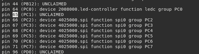
Go to /sys/kernel/debug/pinctrl/2000000.pinctrl/pinmux-pins, and get the number of your pin
—
First try
$ dmesg | grep mcp251x
[   50.140434] CAN device driver interface
[   51.697205] mcp251x spi0.0: MCP251x didn't enter in conf mode after reset
[   51.817128] mcp251x spi0.0: Probe failed, err=110
[   51.821975] mcp251x: probe of spi0.0 failed with error -110
// IN spi@4026000

mcp2515 {
        reg = <0>;		// SPI 1
        compatible = "microchip,mcp2515";
        pinctrl-names = "default";
        pinctrl-0 = <0x85>;
        spi-max-frequency = <10000000>;
        interrupt-parent = <0x22>; // pinctrl@2000000
        interrupts = <0 65 2>; // IRQ LINE, try with <0 65 2>
        clocks = <0x81>;
        status = "okay";
};
With this configuratoin it hangs when I try the command to initialise it. This means that the interrupt is not correctly configured.
Stucked again
- nice overlay example of CAN on raspberry
- I am stucked and I dont know how to continue. But what if you delete all the configuration related to the spi, and it is only used by the can. I think the problem is there.
Asked on ARMBIAN FORUM
I checked the modules loaded in the kernel and it seems is loaded:
root@ubuntu:~# lsmod | grep mcp251x
mcp251x                36864  0
can_dev                57344  1 mcp251x
root@ubuntu:~# modinfo mcp251x
filename:       /lib/modules/5.17.0-1003-allwinner/kernel/drivers/net/can/spi/mcp251x.ko
license:        GPL v2
description:    Microchip 251x/25625 CAN driver
author:         Chris Elston <celston@katalix.com>, Christian Pellegrin <chripell@evolware.org>
srcversion:     D69A1071669D84785288612
alias:          of:N*T*Cmicrochip,mcp25625C*
alias:          of:N*T*Cmicrochip,mcp25625
alias:          of:N*T*Cmicrochip,mcp2515C*
alias:          of:N*T*Cmicrochip,mcp2515
alias:          of:N*T*Cmicrochip,mcp2510C*
alias:          of:N*T*Cmicrochip,mcp2510
alias:          spi:mcp25625
alias:          spi:mcp2515
alias:          spi:mcp2510
depends:        can-dev
intree:         Y
name:           mcp251x
vermagic:       5.17.0-1003-allwinner SMP mod_unload modversions riscv
root@ubuntu:~find /sys/ -name "*mcp251x*"*"
/sys/kernel/btf/mcp251x
/sys/bus/spi/drivers/mcp251x
/sys/module/mcp251x
/sys/module/mcp251x/drivers/spi:mcp251x
/sys/module/can_dev/holders/mcp251x
Working!
It is working with the next configuration! I am going to cry:
can0_osc_fixed {
    compatible = "fixed-clock";
    #clock-cells = <0>;
    clock-frequency  = <8000000>;
    phandle = <0x81>;
};

can0_pin_irq {
        pins = "PD17";
        function = "irq";
        phandle = <0x85>;
        bias-pull-up;
};

mcp2515 {
        reg = <0>;		// SPI 1 100% is 0
        compatible = "microchip,mcp2515";
        pinctrl-names = "default";
        pinctrl-0 = <0x85>;
        spi-max-frequency = <10000000>;
        interrupt-parent = <0x22>; // pinctrl@2000000
        interrupts = <3 17 8>; // PD17 IRQ LINE, try with <0 65 2>
        clocks = <0x81>;
        status = "okay";
};