A lock-in amplifier is a phase-sensitive detector, it acts a super narrow filter, discriminating the noise. It is used in scenarios with high noise, even noise that is hundred times bigger than the signal. This filter is that good because of its narrow behaviour (0.01 Hz as an example).
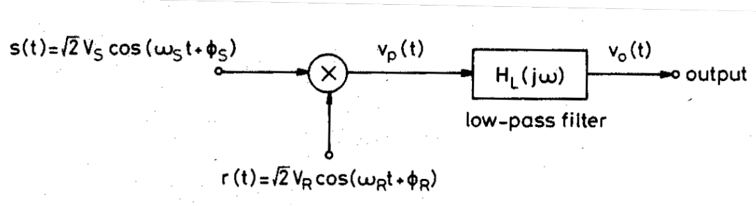
A lock-in amplifier basically is a multiplication between a reference signal to the input signal. A basic diagram would be the next one:
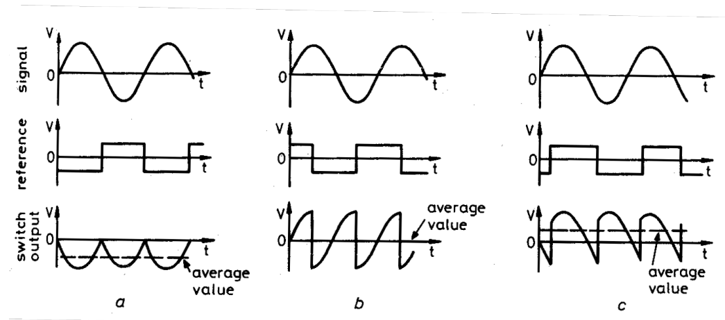
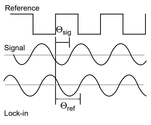
Normally the reference signal is going to be a generated by a square wave with a certain phase. On more complex designs this square signal phase is generated with a PLL in order to delete noises when the input signal phase changes quickly.
This signals can be represented as, \(s(t)\) the input signal and \(r(t)\) the reference signal. $$ s(t) = \sqrt{2} V_{sig} \cdot \cos{(\omega_s t + \phi_{sig})} \\ r(t) = \sqrt{2} V_{ref} \cdot \cos{(\omega_r t + \phi_{ref})} $$ After the multiplication it would be:
$$ v_s(t) = s(t) \cdot r(t) = V_{sig} \cdot V_{ref} \cdot [\cos{([w_s - w_r]t + \phi_{sig} - \phi_{ref})} + \cos{([w_s + w_r]t + \phi_{sig} + \phi_{ref})}] \\ = V_{sig} \cdot V_{ref} \cdot [\cos{(\phi_{sig} - \phi_{ref})} + \cos{(2 w_s t + \phi_{sig} + \phi_{ref})}] $$ The frequencies of the input signal and the reference signal are the same. The output of the multiplication is introducced to a low pass filter that deletes the AC signal.
$$ v_s = V_{sig} \cdot V_{ref} \cdot \cos{(\phi_{sig} - \phi_{ref})} $$ The difference in the phase will have a great impact in the resulting signal: