I create an excel to calculate the link budget. Is can be downloaded here
- SPACECRAFT SYSTEMS ENGINEERING, John Wiley, Section 12.2.10
For the link budget it is not necessary to define the bandwidth, the snr is in dBHz. The important is to define the minimum SNR that is dependant on the desire BER; that is given by the specified modulation.
Free-space loss
The free-space loss os the attenuation between two isotropic antennas separated by a distance r:
$$ L_{FS} = (4 \pi r / \lambda)^2 $$
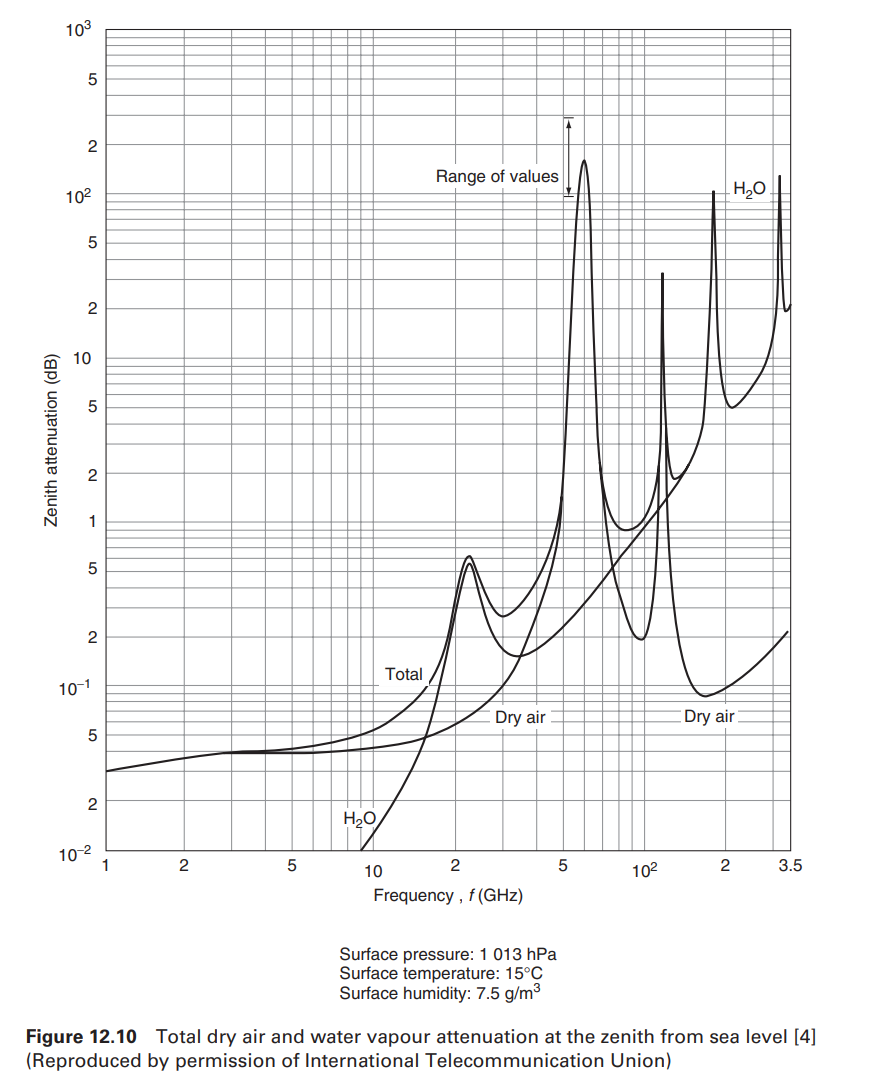
Atmospheric attenuation

Noise
It is defined the Noise power density
$$ \text{Noise power density} = N_0 = k \cdot T_{sys} \cdot B \\ k = \text{Boltzmann constant} = 1.38 \cdot 10^{-23} \\ B = \text{Bandwidth} $$
Noise from an amplifier
We can define the noise of an amplifier with two different methods, thermal noise power: $$ P_{out}(f) = G k (T + T_{amp}) \\ P_{out}(f) = F G k T_0 \\ \Rightarrow F = 1 + (T_{amp} / T_0) $$
Normally we set \(T_0 = 290 K\).
Noise of an attenuator: $$ f = 1 + \frac{T_e}{T_0} = 1 + \frac{T}{T_0} \cdot (l -1) \\ l = \text{loses} $$
Cuadripoles in cascade defines: $$ T_e = T_1 + \frac{T_2}{g_1} + \frac{T_3}{g_1 g_2} + … + \frac{T_N}{g_1 g_2 … g_{N-1}} $$ Noise figure: $$ f = f_1 + \frac{f_2 - 1}{g_1} + \frac{f_3 - 1}{g_1 g_2} + … + \frac{f_{N-1}}{g_1 g_2 … g_{N-1}} $$
$$ f = f_a + (f_c -1) + l_c (f_t -1) + l_c l_t (f_r - 1) \\ f_a = \text{External noise factor} \\ f_c = \text{Noiser factor of the losses of the antenna} \\ l_c = \text{loses of the circuit of the antenna} \\ f_t = \text{Noise factor related to the transmission lines} \\ l_t = \text{loses of the transmission line} \\ f_r = \text{Noise factor of the receiver} $$
Satellite Link Budget
$$ P_{RX} = P_T \cdot G_T \cdot (\frac{1}{L_{TX}}) \cdot (\frac{1}{L_{FS}}) \cdot (\frac{1}{L_A}) \cdot G_{RX} \cdot (\frac{1}{L_{RX}}) \\ L_{TX} = \text{Transmitter losses} \ [dBm] \\ L_{FS} = \text{Losses in free space} \\ L_A = \text{Atmospheric attenuation factor} \\ G_{RX} = \text{Reception Gain} \\ L_{RX} = \text{Receiver losses} \ [dBm] $$
In logarithmic is:
$$ P_{RX} = P_{TX} + G_{TX} - L_{TX} - L_{FS} - L_{M} + G_{RX} - L_{RX} \ P_{RX} = \text{Received power} \ [dBm] \\ P_{TX} = \text{Transmitted output power} \ [dBm] \\ G_{TX} = \text{Transmitter antenna gain} \ [dBi] \\ L_{TX} = \text{Transmitter losses (cable loss and impedance mitmatch)} \ [dB] \\ L_{FS} = \text{Free space loss} \ [dB] \\ L_M = \text{Miscellaneous losses (fading margin, body loss, polarization mismatch, other losses)} \ [dB] \\ G_{RX} = \text{Received antenna gain} \ [dBi] \\ L_{RX} = \text{Receiver losses (cable loss and impedance mitmatch)} \ [dB] $$ It is defined the Noise power density $$ \text{Noise power density} = N_0 = k \cdot T_{sys} $$ Expressed in signal-to-noise-power-density:
$$ C / N_0 = P_T \cdot G_T \cdot (\frac{1}{L_{FS}}) \cdot (\frac{1}{L_A}) \cdot G_R \cdot (\frac{1}{k \cdot T_{sys}}) \\ T_{sys} = \text{System temperature in the receptor} $$ The signal-to-noise-power-density ratio is related to the bit energy to noise power density:
$$ E_b / N_0 = C / N_0 \cdot 1 / R $$ Where R is the channel data rate.
$$ \frac{S}{N} = \frac{E_b}{N_0} \frac{f_b}{B} \
B = \text{Channel bandwidth} \\ f_b = \text{Channel data rate} $$ The most important aspect of a given modulation technique is the Signal-to-Noise Ratio (SNR) necessary for a receiver to achieve a specified level of reliability in terms of BER. In general, the modulation technique dictates the required system bandwidth.
Shannon theory
$$ C = 2B \cdot \log_2{M} $$ C is the capacity in bits per second, B is the frequency bandwidth in Herts, and M is the number of levels a single symbol can take on.
For example in BPSK, M = 2.
With the shannon theory you get the maximum capacity of the channel. Used in 20220111 - Error correcting - Project - Low Density Parity Check. $$ C = W \cdot \log_2 (1 + SNR) \quad [bits/s] \\ W = \text{Bandwidth [Hz]} \\ SNR = \text{Signal over noise [lineal units]} $$
Ground station characterization
The ground station is defined using the diameter, the EIRP and the G/T.