I realised that the function analogRead is super slow, in this note I am going to try to make is faster.
First example
#include <Arduino.h>

// Analog pin
#define AN_PIN A0

// Logic Analizer
#define LA_CH0 D7
#define LA_CH1 D8
#define LA_CH2 D9

int val = 0;

void setup() {
  // put your setup code here, to run once:
  Serial.begin(9600);

  pinMode(LA_CH0, OUTPUT);
  pinMode(LA_CH1, OUTPUT);
  pinMode(LA_CH2, OUTPUT);
}

void loop() {
  // put your main code here, to run repeatedly:
  digitalWrite(LA_CH0, HIGH);
  val = analogRead(AN_PIN);
  digitalWrite(LA_CH0, LOW);


  Serial.println(val);
  delay(1);
}
And the time it takes to do the analogRead is 50us.
From reading on internet, it seems that is not that easy to increase the sampling frequency. I am going to do a example on cubeIDE to see if I am able to increase the frequency there.
STM32 cube ide without DMA
The first example is to read analog value without DMA:
/* Infinite loop */
  /* USER CODE BEGIN WHILE */
  while (1)
  {
    /* USER CODE END WHILE */

    /* USER CODE BEGIN 3 */
	  HAL_GPIO_WritePin(GPIOA, GPIO_PIN_8, GPIO_PIN_SET);
	  HAL_ADC_Start(&hadc1);
	  HAL_ADC_PollForConversion(&hadc1, HAL_MAX_DELAY);
	  raw = HAL_ADC_GetValue(&hadc1);
	  HAL_GPIO_WritePin(GPIOA, GPIO_PIN_8, GPIO_PIN_RESET);
	  HAL_Delay(10);
  }
  /* USER CODE END 3 */
This takes to read -> 5.3uS
With DMA
/* USER CODE BEGIN WHILE */
  while (1)
  {
    /* USER CODE END WHILE */

    /* USER CODE BEGIN 3 */
    HAL_GPIO_WritePin(GPIOA, GPIO_PIN_8, GPIO_PIN_SET);

    HAL_ADC_Start_DMA(&hadc1,(uint32_t*)&val,1);

	  //HAL_ADC_Start(&hadc1);
	  //HAL_ADC_PollForConversion(&hadc1, HAL_MAX_DELAY);
	  //raw = HAL_ADC_GetValue(&hadc1);

	  HAL_GPIO_WritePin(GPIOA, GPIO_PIN_8, GPIO_PIN_RESET);
	  HAL_Delay(10);
  }
  /* USER CODE END 3 */
This takes to read -> 7uS
You can configure more adc’s in the dma like:
 /* USER CODE BEGIN WHILE */
  while (1)
  {
    /* USER CODE END WHILE */

    /* USER CODE BEGIN 3 */
    HAL_GPIO_WritePin(GPIOA, GPIO_PIN_8, GPIO_PIN_SET);

    HAL_ADC_Start_DMA(&hadc1,(uint32_t*) val,3);

	  //HAL_ADC_Start(&hadc1);
	  //HAL_ADC_PollForConversion(&hadc1, HAL_MAX_DELAY);
	  //raw = HAL_ADC_GetValue(&hadc1);

	  HAL_GPIO_WritePin(GPIOA, GPIO_PIN_8, GPIO_PIN_RESET);
	  HAL_Delay(10);
  }
  /* USER CODE END 3 */
And this transaction takes just, that is reading 3 different inputs 4.8us
Arduino code
- Here a forum post that the guy did something similar
- And here the oficial documentation about HAL
- One working example
Just copying and paste the previous code into arduino is able to compile.… but there is not output on the val function. That means that the ADC has not been configured correctly.
The steps are kinda:
- Put the HAL_ADC_MODULE_ONLY on the build opts.
- import code from
main.c,stm32....hal_msp.candstm32....hal_it.c - Is necessary to write HAL_ADC_MspInit
And the next code works, I can see the data on the debug mode:
#include <Arduino.h>
// Analog pin
#define AN_PIN A0
// Logic Analizer
#define LA_CH0 D7
#define LA_CH1 D8
#define LA_CH2 D9
//STM32 CODE
ADC_HandleTypeDef hadc1;
DMA_HandleTypeDef hdma_adc1;
uint16_t val[10] = {0};
static void MX_DMA_Init(void);
static void MX_ADC1_Init(void);
extern "C" void HAL_ADC_MspDeInit(ADC_HandleTypeDef* hadc);
extern "C" void HAL_ADC_MspInit(ADC_HandleTypeDef* hadc);
extern "C" void DMA2_Stream0_IRQHandler(void);
void setup() {
// put your setup code here, to run once:
Serial.begin(9600);
MX_DMA_Init();
MX_ADC1_Init();
pinMode(LA_CH0, OUTPUT);
pinMode(LA_CH1, OUTPUT);
pinMode(LA_CH2, OUTPUT);
/* Start ADC conversion on regular group with transfer by DMA */
if (HAL_ADC_Start_DMA(&hadc1,
(uint32_t*) val,
10
) != HAL_OK) {
/* Start Error */
Error_Handler();
}
}
void loop() {
// put your main code here, to run repeatedly:
digitalWrite(LA_CH0, HIGH);
HAL_ADC_Start_DMA(&hadc1,(uint32_t*) val,10);
digitalWrite(LA_CH0, LOW);
Serial.print("Val0");
Serial.println(val[0]);
delay(100);
}
// STM32 CODE
/**
* @brief ADC1 Initialization Function
* @param None
* @retval None
*/
static void MX_ADC1_Init(void)
{
/* USER CODE BEGIN ADC1_Init 0 */
/* USER CODE END ADC1_Init 0 */
ADC_ChannelConfTypeDef sConfig = {0};
/* USER CODE BEGIN ADC1_Init 1 */
/* USER CODE END ADC1_Init 1 */
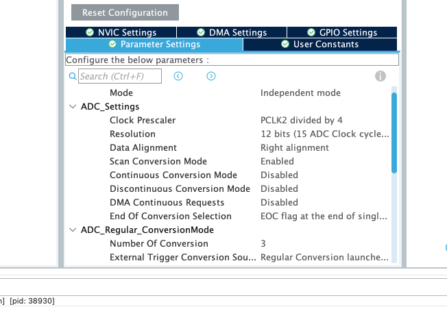
/** Configure the global features of the ADC (Clock, Resolution, Data Alignment and number of conversion)
*/
hadc1.Instance = ADC1;
hadc1.Init.ClockPrescaler = ADC_CLOCK_SYNC_PCLK_DIV4;
hadc1.Init.Resolution = ADC_RESOLUTION_12B;
hadc1.Init.ScanConvMode = ENABLE;
hadc1.Init.ContinuousConvMode = DISABLE;
hadc1.Init.DiscontinuousConvMode = DISABLE;
hadc1.Init.ExternalTrigConvEdge = ADC_EXTERNALTRIGCONVEDGE_NONE;
hadc1.Init.ExternalTrigConv = ADC_SOFTWARE_START;
hadc1.Init.DataAlign = ADC_DATAALIGN_RIGHT;
hadc1.Init.NbrOfConversion = 10;
hadc1.Init.DMAContinuousRequests = DISABLE;
hadc1.Init.EOCSelection = ADC_EOC_SINGLE_CONV;
if (HAL_ADC_Init(&hadc1) != HAL_OK)
{
Error_Handler();
}
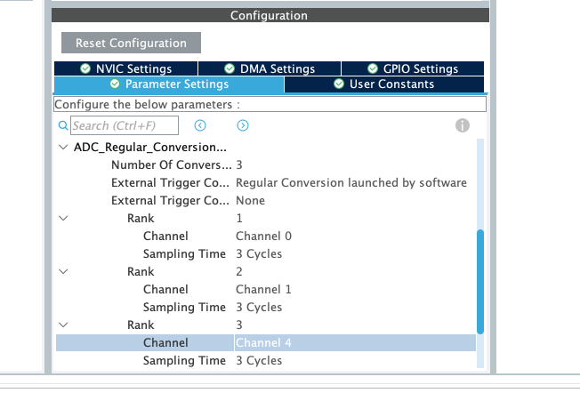
/** Configure for the selected ADC regular channel its corresponding rank in the sequencer and its sample time.
*/
sConfig.Channel = ADC_CHANNEL_0;
sConfig.Rank = 1;
sConfig.SamplingTime = ADC_SAMPLETIME_3CYCLES;
if (HAL_ADC_ConfigChannel(&hadc1, &sConfig) != HAL_OK)
{
Error_Handler();
}
/** Configure for the selected ADC regular channel its corresponding rank in the sequencer and its sample time.
*/
sConfig.Channel = ADC_CHANNEL_1;
sConfig.Rank = 2;
if (HAL_ADC_ConfigChannel(&hadc1, &sConfig) != HAL_OK)
{
Error_Handler();
}
/** Configure for the selected ADC regular channel its corresponding rank in the sequencer and its sample time.
*/
sConfig.Channel = ADC_CHANNEL_4;
sConfig.Rank = 3;
if (HAL_ADC_ConfigChannel(&hadc1, &sConfig) != HAL_OK)
{
Error_Handler();
}
/** Configure for the selected ADC regular channel its corresponding rank in the sequencer and its sample time.
*/
sConfig.Channel = ADC_CHANNEL_5;
sConfig.Rank = 4;
if (HAL_ADC_ConfigChannel(&hadc1, &sConfig) != HAL_OK)
{
Error_Handler();
}
/** Configure for the selected ADC regular channel its corresponding rank in the sequencer and its sample time.
*/
sConfig.Channel = ADC_CHANNEL_6;
sConfig.Rank = 5;
if (HAL_ADC_ConfigChannel(&hadc1, &sConfig) != HAL_OK)
{
Error_Handler();
}
/** Configure for the selected ADC regular channel its corresponding rank in the sequencer and its sample time.
*/
sConfig.Channel = ADC_CHANNEL_10;
sConfig.Rank = 6;
if (HAL_ADC_ConfigChannel(&hadc1, &sConfig) != HAL_OK)
{
Error_Handler();
}
/** Configure for the selected ADC regular channel its corresponding rank in the sequencer and its sample time.
*/
sConfig.Channel = ADC_CHANNEL_11;
sConfig.Rank = 7;
if (HAL_ADC_ConfigChannel(&hadc1, &sConfig) != HAL_OK)
{
Error_Handler();
}
/** Configure for the selected ADC regular channel its corresponding rank in the sequencer and its sample time.
*/
sConfig.Channel = ADC_CHANNEL_12;
sConfig.Rank = 8;
if (HAL_ADC_ConfigChannel(&hadc1, &sConfig) != HAL_OK)
{
Error_Handler();
}
/** Configure for the selected ADC regular channel its corresponding rank in the sequencer and its sample time.
*/
sConfig.Channel = ADC_CHANNEL_13;
sConfig.Rank = 9;
if (HAL_ADC_ConfigChannel(&hadc1, &sConfig) != HAL_OK)
{
Error_Handler();
}
/** Configure for the selected ADC regular channel its corresponding rank in the sequencer and its sample time.
*/
sConfig.Channel = ADC_CHANNEL_14;
sConfig.Rank = 10;
if (HAL_ADC_ConfigChannel(&hadc1, &sConfig) != HAL_OK)
{
Error_Handler();
}
/* USER CODE BEGIN ADC1_Init 2 */
/* USER CODE END ADC1_Init 2 */
}
/**
* Enable DMA controller clock
*/
static void MX_DMA_Init(void)
{
/* DMA controller clock enable */
__HAL_RCC_DMA2_CLK_ENABLE();
/* DMA interrupt init */
/* DMA2_Stream0_IRQn interrupt configuration */
HAL_NVIC_SetPriority(DMA2_Stream0_IRQn, 0, 0);
HAL_NVIC_EnableIRQ(DMA2_Stream0_IRQn);
}
/**
* @brief ADC MSP Initialization
* This function configures the hardware resources used in this example
* @param hadc: ADC handle pointer
* @retval None
*/
extern "C" void HAL_ADC_MspInit(ADC_HandleTypeDef* hadc)
{
GPIO_InitTypeDef GPIO_InitStruct = {0};
if(hadc->Instance==ADC1)
{
/* USER CODE BEGIN ADC1_MspInit 0 */
/* USER CODE END ADC1_MspInit 0 */
/* Peripheral clock enable */
__HAL_RCC_ADC1_CLK_ENABLE();
__HAL_RCC_GPIOC_CLK_ENABLE();
__HAL_RCC_GPIOA_CLK_ENABLE();
/**ADC1 GPIO Configuration
PC0 ------> ADC1_IN10
PC1 ------> ADC1_IN11
PC2 ------> ADC1_IN12
PC3 ------> ADC1_IN13
PA0-WKUP ------> ADC1_IN0
PA1 ------> ADC1_IN1
PA4 ------> ADC1_IN4
PA5 ------> ADC1_IN5
PA6 ------> ADC1_IN6
PC4 ------> ADC1_IN14
*/
GPIO_InitStruct.Pin = GPIO_PIN_0|GPIO_PIN_1|GPIO_PIN_2|GPIO_PIN_3
|GPIO_PIN_4;
GPIO_InitStruct.Mode = GPIO_MODE_ANALOG;
GPIO_InitStruct.Pull = GPIO_NOPULL;
HAL_GPIO_Init(GPIOC, &GPIO_InitStruct);
GPIO_InitStruct.Pin = GPIO_PIN_0|GPIO_PIN_1|GPIO_PIN_4|GPIO_PIN_5
|GPIO_PIN_6;
GPIO_InitStruct.Mode = GPIO_MODE_ANALOG;
GPIO_InitStruct.Pull = GPIO_NOPULL;
HAL_GPIO_Init(GPIOA, &GPIO_InitStruct);
/* ADC1 DMA Init */
/* ADC1 Init */
hdma_adc1.Instance = DMA2_Stream0;
hdma_adc1.Init.Channel = DMA_CHANNEL_0;
hdma_adc1.Init.Direction = DMA_PERIPH_TO_MEMORY;
hdma_adc1.Init.PeriphInc = DMA_PINC_DISABLE;
hdma_adc1.Init.MemInc = DMA_MINC_ENABLE;
hdma_adc1.Init.PeriphDataAlignment = DMA_PDATAALIGN_HALFWORD;
hdma_adc1.Init.MemDataAlignment = DMA_MDATAALIGN_HALFWORD;
hdma_adc1.Init.Mode = DMA_CIRCULAR;
hdma_adc1.Init.Priority = DMA_PRIORITY_LOW;
hdma_adc1.Init.FIFOMode = DMA_FIFOMODE_DISABLE;
if (HAL_DMA_Init(&hdma_adc1) != HAL_OK)
{
Error_Handler();
}
__HAL_LINKDMA(hadc,DMA_Handle,hdma_adc1);
/* USER CODE BEGIN ADC1_MspInit 1 */
/* USER CODE END ADC1_MspInit 1 */
}
}
/**
* @brief ADC MSP De-Initialization
* This function freeze the hardware resources used in this example
* @param hadc: ADC handle pointer
* @retval None
*/
extern "C" void HAL_ADC_MspDeInit(ADC_HandleTypeDef* hadc)
{
if(hadc->Instance==ADC1)
{
/* USER CODE BEGIN ADC1_MspDeInit 0 */
/* USER CODE END ADC1_MspDeInit 0 */
/* Peripheral clock disable */
__HAL_RCC_ADC1_CLK_DISABLE();
/**ADC1 GPIO Configuration
PC0 ------> ADC1_IN10
PC1 ------> ADC1_IN11
PC2 ------> ADC1_IN12
PC3 ------> ADC1_IN13
PA0-WKUP ------> ADC1_IN0
PA1 ------> ADC1_IN1
PA4 ------> ADC1_IN4
PA5 ------> ADC1_IN5
PA6 ------> ADC1_IN6
PC4 ------> ADC1_IN14
*/
HAL_GPIO_DeInit(GPIOC, GPIO_PIN_0|GPIO_PIN_1|GPIO_PIN_2|GPIO_PIN_3
|GPIO_PIN_4);
HAL_GPIO_DeInit(GPIOA, GPIO_PIN_0|GPIO_PIN_1|GPIO_PIN_4|GPIO_PIN_5
|GPIO_PIN_6);
/* ADC1 DMA DeInit */
HAL_DMA_DeInit(hadc->DMA_Handle);
/* USER CODE BEGIN ADC1_MspDeInit 1 */
/* USER CODE END ADC1_MspDeInit 1 */
}
}
/**
* @brief This function handles DMA2 stream0 global interrupt.
*/
extern "C" void DMA2_Stream0_IRQHandler(void)
{
/* USER CODE BEGIN DMA2_Stream0_IRQn 0 */
/* USER CODE END DMA2_Stream0_IRQn 0 */
HAL_DMA_IRQHandler(&hdma_adc1);
/* USER CODE BEGIN DMA2_Stream0_IRQn 1 */
/* USER CODE END DMA2_Stream0_IRQn 1 */
}
And now it just 2us. Suuuper dope.
The pin configuration is the next one:
    /**ADC1 GPIO Configuration
    PC0     ------> ADC1_IN10
    PC1     ------> ADC1_IN11
    PC2     ------> ADC1_IN12
    PC3     ------> ADC1_IN13
    PA0-WKUP     ------> ADC1_IN0
    PA1     ------> ADC1_IN1
    PA4     ------> ADC1_IN4
    PA5     ------> ADC1_IN5
    PA6     ------> ADC1_IN6
    PC4     ------> ADC1_IN14
    */
Circular mode and loop all the time
It is possible to configure the DMA to execute in a loop with each start_DMA.
Interrupt
When using DMA and AD, the interrupt is called when you define the next function:
/* USER CODE BEGIN 4 */
void HAL_ADC_ConvCpltCallback(ADC_HandleTypeDef* hadc)
{

	HAL_GPIO_WritePin(GPIOC, GPIO_PIN_7, led_irq);
	led_irq = !led_irq;

	__NOP(); //Line reached only if transfer was successful. Toggle a breakpoint here
}
/* USER CODE END 4 */
Sample rate
In continuous mode and dma I get the data in 5us.
Without continuos mode and interrupt I get the data in 15us.