Relevant links for this note:
Material required
- Prototype subsystem board
- ESP-Prog, is a external programmer
- Arduino IDE installed
Getting started - Blink LED
The first example is to blink a led, that way we are going to verify that we are able to upload the code. The steps are:
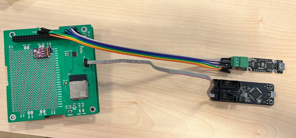
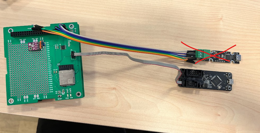
- Connect the ESP-Prog to the prototype subsystem board. In this picture is also connected the uCAN that is not required for this example:
- Connect the ESP-Prog to the computer with a microUSB cable. You should be able to see the prototype system Power led high.
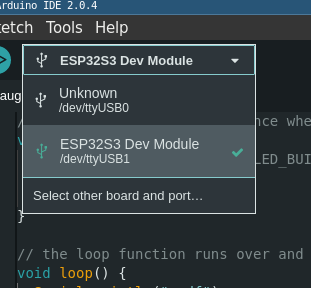
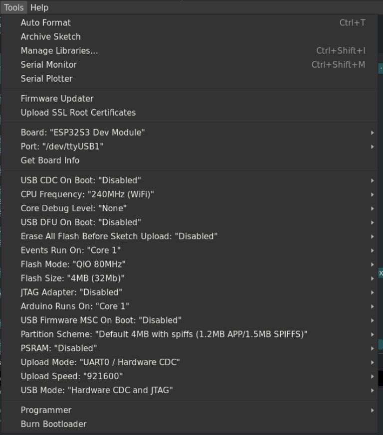
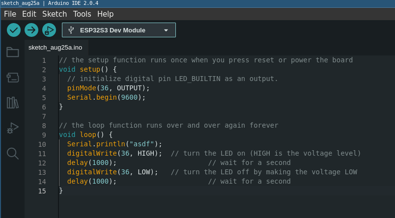
- Go to arduino IDE, and upload the next code to the board. It is the ESP32-DevKit. The builtin led is connected to the GPIO36 of the ESP32S3.
// the setup function runs once when you press reset or power the board
void setup() {
  // initialize digital pin LED_BUILTIN as an output.
  pinMode(36, OUTPUT);
  Serial.begin(9600);
}

// the loop function runs over and over again forever
void loop() {
  Serial.println("asdf");
  digitalWrite(36, HIGH);  // turn the LED on (HIGH is the voltage level)
  delay(1000);                      // wait for a second
  digitalWrite(36, LOW);   // turn the LED off by making the voltage LOW
  delay(1000);                      // wait for a second
}
- You should be able to see the led blinking
Send messages over CAN network using the CFP library
The wiring is the next one: