Description
The prototype subsystem is a open PCB with empty space for soldering external modules, and the minium components to interact with the other subsystems. It has a microcontroller, the ESP32S3, that will be used for the communication with the satellite and for the external modules that may be installed. This board is very similar to the COMMS subsystems, but without the LoRa transceiver.
In order to flash this subsystem is necessary to use an external programmer like the ESP-Prog.
PCB Overview
Blocks description
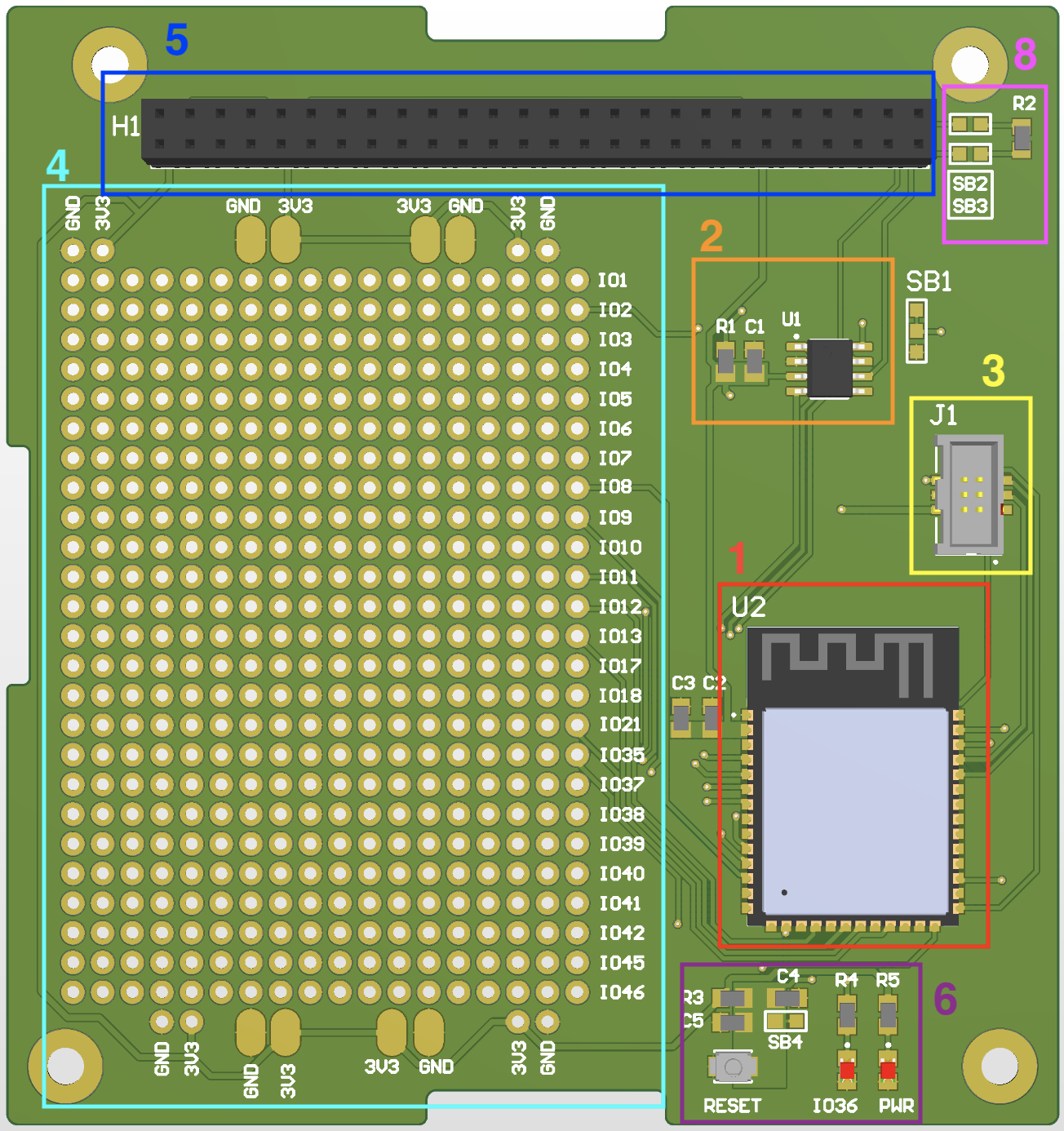
- 1 - Red box: Is the microcontroller of the subsystem, the ESP32S3.
- 2 - Orange box: CAN transceiver. It is the SN65HVD234D. It interfaces between a Controller Area Network (CAN) controller and the physical CAN bus. It acts as a mediator, converting the digital signals from the CAN controller into the appropriate electrical signals suitable for transmission over the CAN bus, and vice versa.
- 3 - Yellow box: The ESP-Prog interface. Is used to flash the software on the microcontroller using the external programmer ESP-Prog.
- 4 - Cyan box: A breadboard to solder modules. At the right of the grid you have the different Input Outputs of the microcontroller, and on top/bottom the connections for powering the modules. As an example you could add a temperature sensor and get the data from the microcontroller.
- 5 - Blue box: It is the Common bus of the satellite. The power is delivered from this bus.
- 6 - Purple box: This board has 2 Leds, one is “ON” where there is power in the system, and the other is attached to IO36 of the microcontroller. The button SW1 is a reset button.
- 8 - Pink box : CAN optional terminantion resistors. A CAN network needs to have 120 ohms resistors on the end of the network. The very top Subsystem and the bottom subsystem of the satellite needs to be populated with 120 Ohm resistor and the solderbridge close.