Another source of useful information
I am going to explain how to know the values of the Pi Filter for antenna tunning in a PCB.
The steps are:
- Calibration
- Measure
- Correct
PCB Design for correct RF traces
After failing a bit in my first iteration there are some advices:
- Ask the manufacturer to tune the traces to 50 Ohm
- The pi filter as close as possible to the antenna
- If the antenna is 50 Ohm is not necessary to put pi filter, but it is not usually like this. But the interaction of the components with the antenna is gonna modify the impedance a bit. You would like to put a Pi filter for removing noise, filtering and impendance matching.
- It is essential that the transmission lines are 50 Ohms
- It is essential that the pi filter has the components as close as possible
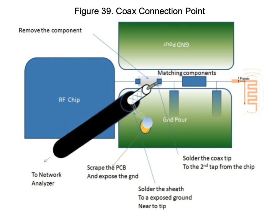
- The calibration of the VNA can be done at the beginning of the pi filter, or in the port of transmission. The important is that the transmission line is known.
- The impedance has to be measured at a point very close to the matching network.
- Use only high-Q components for both capacitors and inductors
- Put a 0ohm resistor before the matching circuit. Is going to be used for calibrating the VNA.
- Use the calculator from JLCPCB And take into account if you are using coplanar wave, or microstrip.
- Dont use the components from the books, they are generic ones, and they are very very bad. I have tried to measure some and they give completly different values than what they should give. That is becuase this components are not rated for radio applications
How to calibrate and use the VNA
The steps are:
- First select what is the stimuli signal
- The configure which signal you want to view
- Then calibrate it with Load, short and these
Calibration
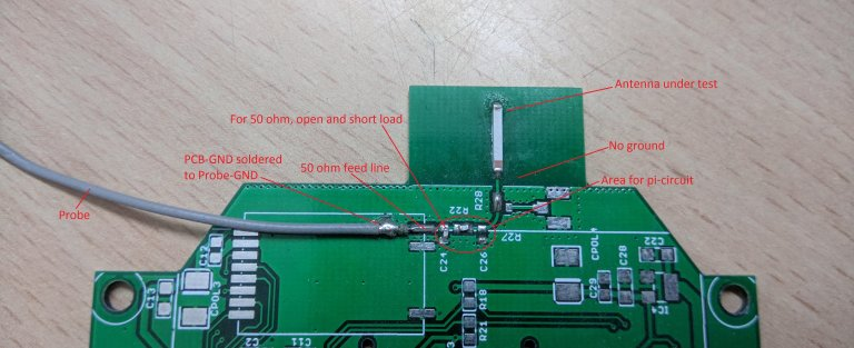
First we solder in the PCB, the antenna we want to use, and a probe in the port of the transceiver. With any component populated in the Pi filter we are going to perform the calibration of the VNA.
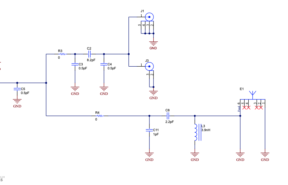
For OPEN calibration, we removed C24, C26, R22, R28 and R27. For SHORT calibration, we put a 0 (zero) ohm resistor at C24 and kept everything else the same and for LOAD calibration, a 50 ohm resistor was installed at C24 keeping everything else the same. This generated the calibration which we used for antenna measurement.
Measure
Then we put 0Ohm resistors on the line, and we measure the impedance of the antenna. Ideally it should be at 50Ohm in the frequency we need. But the PCB with introduce some reactance.
Correct
By adding capacitor, and inductors in the PI filter we are going to be able to tune the antenna.