Description
The On-Board Computer (OBC) subsystem represents a critical printed circuit board (PCB) within the satellite’s architecture. Its primary function is to manage the satellite’s communications, including constructing CCSDS (Consultative Committee for Space Data Systems) packets and facilitating the exchange of telemetry and telecommands with the Communication (COMMS) subsystem. Moreover, this subsystem can be used for processing or calibration of the data if necessary.
It is possible to control this subsystem using UART1 or through Wifi using SSH. The OBC is connected to the different subsystems using CAN through the CAN controller (U2), ensuring robust and reliable data transmission across components.
Designed as a development PCB, the OBC features multiple inputs and outputs, not all of which are essential for the satellite’s primary operations. This design philosophy aims to equip the satellite with the broadest possible capabilities, leveraging the versatility of a Linux-based computing platform to meet a wide array of operational requirements.
PCB Overview
Blocks description
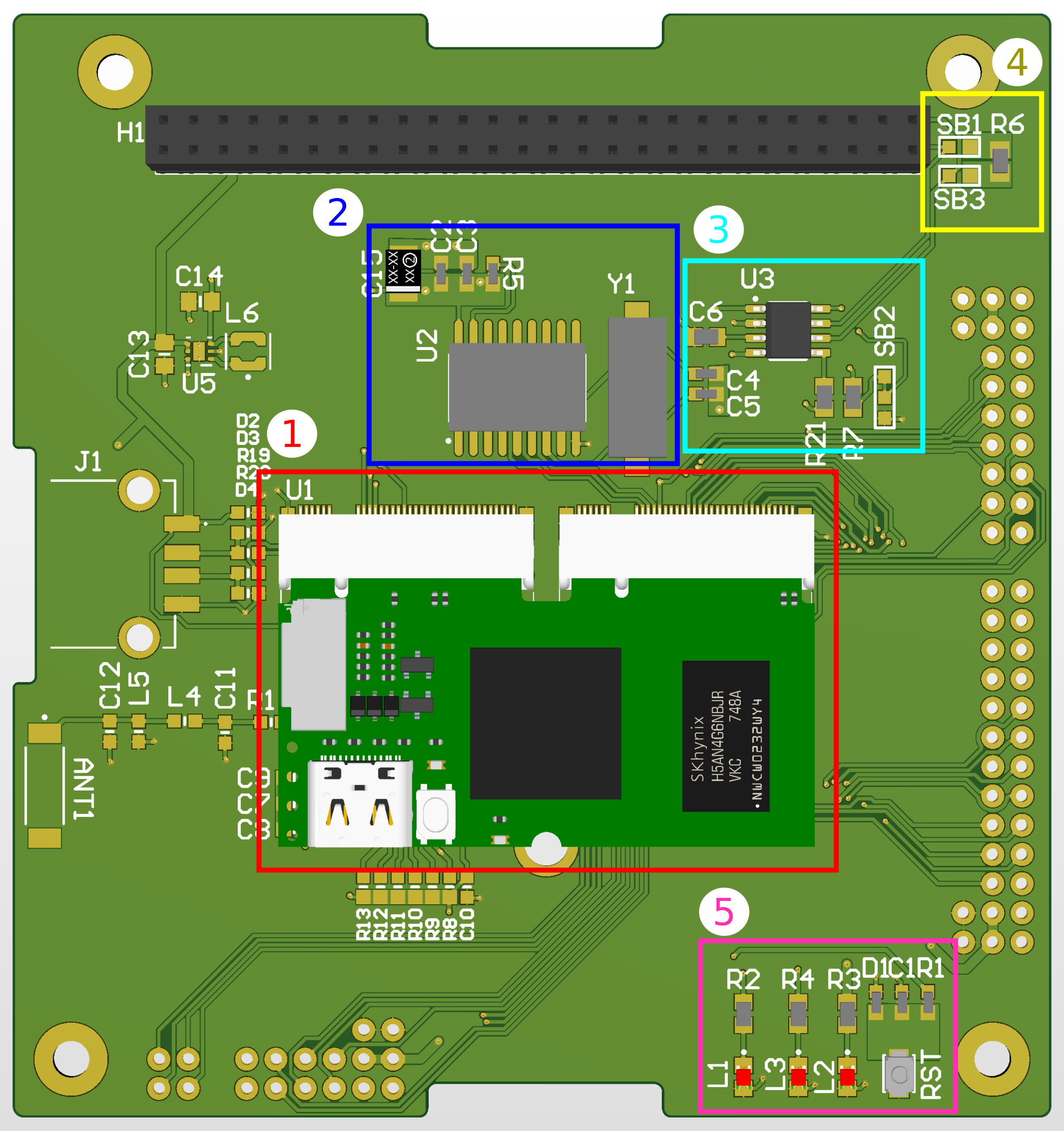
The blocks can be divided into:
- Red 1 - Single Board Computer: It is a Lichee RV compute module. It is a RISCV computer, similar to Raspberry Pi, in a smaller factor. It is running a Linux Operating system which is controlling the communication of the satellite.
- Blue 2 - CAN Controller: It is the MCP2515T-E/SO CAN Controller. It is communication device that manages the transmission and reception of messages over a CAN network.
- Cyan 3 - CAN Transceiver: It is the SN65HVD234D. It interfaces between a Controller Area Network (CAN) controller and the physical CAN bus. It acts as a mediator, converting the digital signals from the CAN controller into the appropriate electrical signals suitable for transmission over the CAN bus, and vice versa.
- Yellow 4 - CAN optional terminantion resistors: A CAN network needs to have 120 ohms resistors on the end of the network. The very top Subsystem and the bottom subsystem of the satellite needs to be populated with 120 Ohm resistor and the solderbridge close.
- Pink 5 - Status LEDs: Indicate some activity from the satellite. L1 is a heartbeat that is active when the device is on. L2 is active when the device has power. L3 is active with the kernel Linux activity.
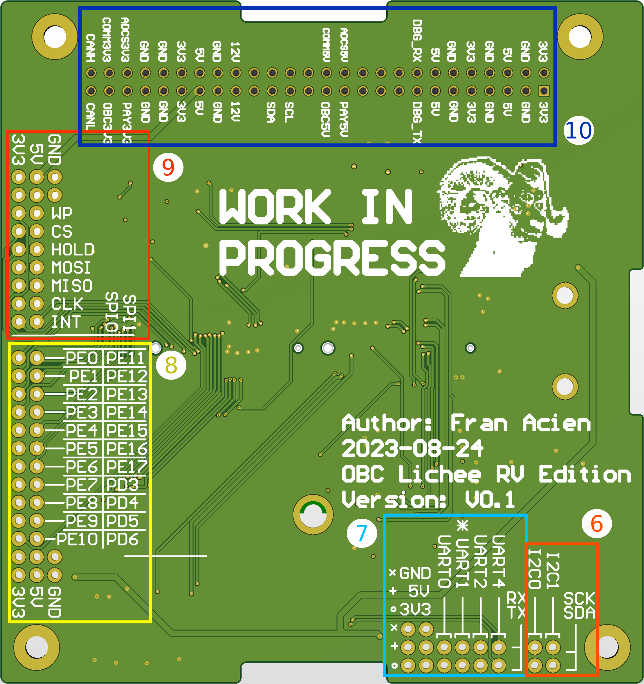
- Red 6 - I2Cs connected to the SBC: It is NOT implemented on the kernel Linux. It is used for debuging and development purposes.
- Cyan 7 - UARTs connected to the SBC: The UART1 is used to control the device over UART. The baud rate is 115200 and lets you to access the terminal. The other channels are NOT implemented on the kernel Linux.
- Yellow 8 - GPIOs connected to the SBC: It is NOT implemented on the kernel Linux. It is used for debuging and development purposes.
- Red 9 - SPIs connected to the SBC: The SPI1 is used by the CAN controller. It is used for debuging and development purposes.
- Blue 10 - PC104 Satellite Common Bus: It is the common bus in which the subsystem receives the power and communicate with the other subsystems.