Relevant links for this note:
- Schematic of the Prototype Subsystem Board V0.1
- ESP32-CFP Library - This library is used to create and receive the CAN messages
Material required
- Prototype subsystem board
- ESP-Prog, is a external programmer
- Arduino IDE installed
- CFP library installed
- uCAN - USB CAN interface
Getting started - Blink LED
The first example is to blink a led, that way we are going to verify that we are able to upload the code. The steps are:
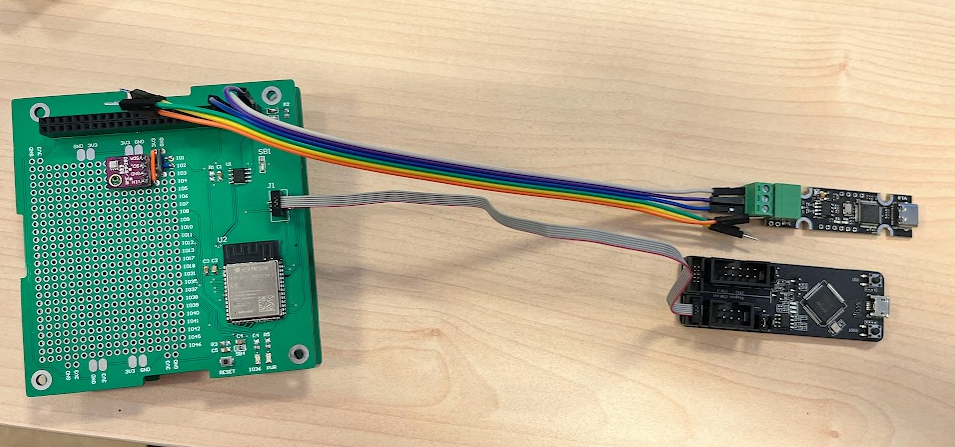
- Connect the ESP-Prog to the prototype subsystem board. In this picture is also connected the uCAN that is not required for this example:
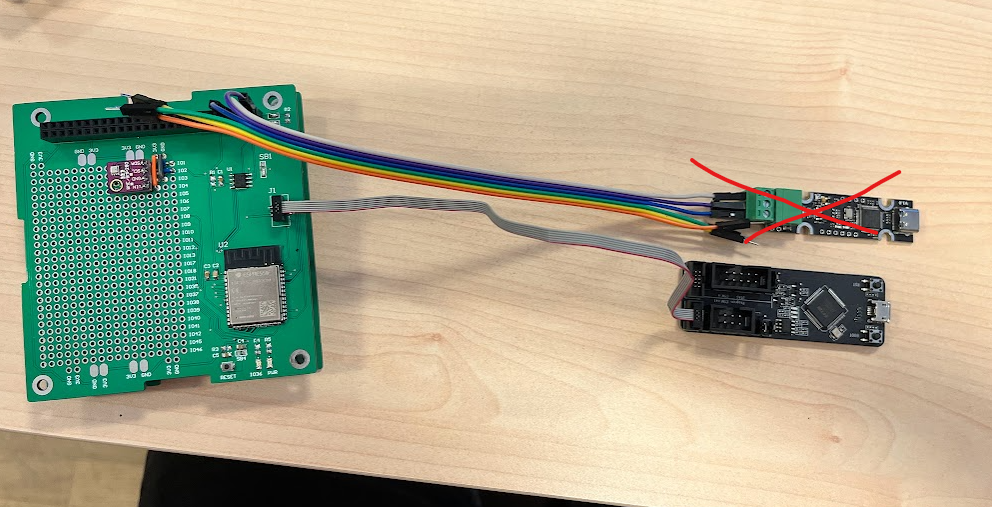
- Connect the ESP-Prog to the computer with a microUSB cable. You should be able to see the prototype system Power led high.
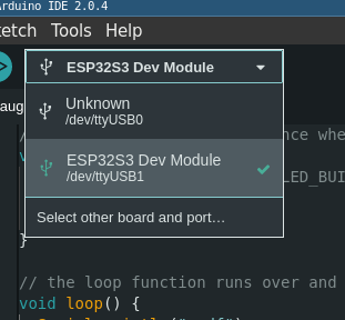
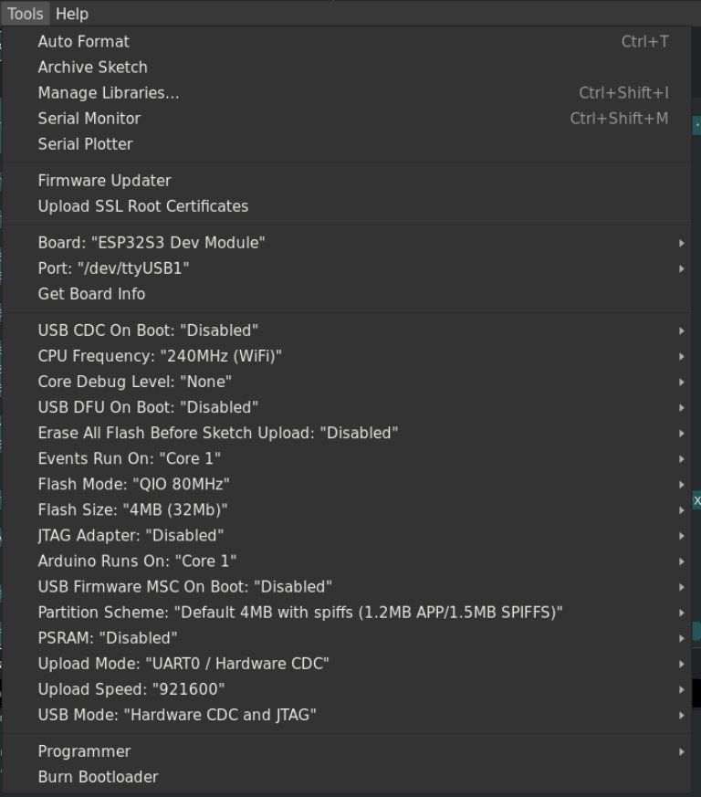
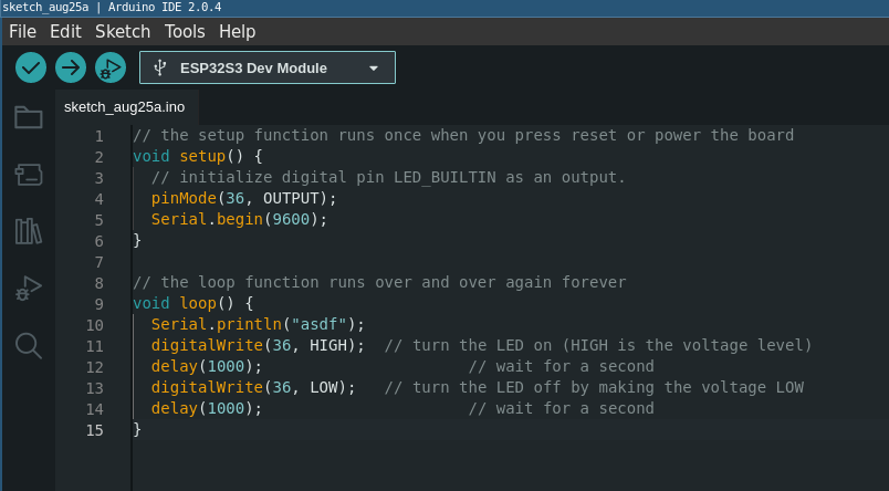
- Go to arduino IDE, and upload the next code to the board. It is the ESP32-DevKit. The builtin led is connected to the GPIO36 of the ESP32S3.
// the setup function runs once when you press reset or power the board
void setup() {
  // initialize digital pin LED_BUILTIN as an output.
  pinMode(36, OUTPUT);
  Serial.begin(9600);
}

// the loop function runs over and over again forever
void loop() {
  Serial.println("asdf");
  digitalWrite(36, HIGH);  // turn the LED on (HIGH is the voltage level)
  delay(1000);                      // wait for a second
  digitalWrite(36, LOW);   // turn the LED off by making the voltage LOW
  delay(1000);                      // wait for a second
}
- You should be able to see the led blinking
Send messages over CAN network using the CFP library
The wiring is the next one:
Connect the uCAN to the computer and configure it as 20230629 - UCAN on EDUSAT.
The code of this example is the next one:
/*
 This example show how to send more than 8 bytes with can usign CFP (CAN Fragmentation Protocol)
*/

#include <Arduino.h>

#include <CFP.h>

#define TX_PIN   14  // Connects to CTX
#define RX_PIN   15  // Connects to CRX

#define CAN_EN_PIN 16

#define SAMPLE_CFP_SOURCE 0
#define SAMPLE_CFP_DESTINATION 1
#define SAMPLE_CFP_ID 404

// Intervall:
#define POLLING_RATE_MS 1000


uint8_t sample_data[] = {0x0, 0x1, 0x2, 0x3, 0x4, 0x5, 0x6, 0x7, 0x8, 0x9, 0xa, 0xb, 0xc, 0xd, 0xe, 0xf, 16, 17};

CAN_CFP_DATA s_packet = {sample_data, sizeof(sample_data)};


static bool driver_installed = false;

//==================================================================================//
void setup() {
  Serial.begin (115200);
  while (!Serial);
  delay (1000);
  Serial.println ("CAN Receiver/Receiver");

  // Enable CAN transceiver
  pinMode(CAN_EN_PIN, OUTPUT);
  digitalWrite(CAN_EN_PIN, HIGH);

  // Initialize configuration structures using macro initializers
  twai_general_config_t g_config = TWAI_GENERAL_CONFIG_DEFAULT((gpio_num_t)TX_PIN, (gpio_num_t)RX_PIN, TWAI_MODE_NORMAL);
  twai_timing_config_t t_config = TWAI_TIMING_CONFIG_500KBITS();  //Look in the api-reference for other speed sets.
  twai_filter_config_t f_config = TWAI_FILTER_CONFIG_ACCEPT_ALL();

  //Install TWAI driver
  if (twai_driver_install(&g_config, &t_config, &f_config) == ESP_OK) {
      printf("Driver installed\n");
  } else {
      printf("Failed to install driver\n");
      return;
  }

  //Start TWAI driver
  if (twai_start() == ESP_OK) {
      printf("Driver started\n");
  } else {
      printf("Failed to start driver\n");
      return;
  }

  // TWAI driver is now successfully installed and started
  driver_installed = true;
}

void loop() {

  sendCFP(s_packet, SAMPLE_CFP_SOURCE, SAMPLE_CFP_DESTINATION, SAMPLE_CFP_ID);

  delay(10000);
}
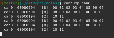
With this example you are sending CAN messages. In order to see this messages you can connect a uCAN to your computer, and configure it like 20230629 - UCAN on EDUSAT. The output should be like next one: