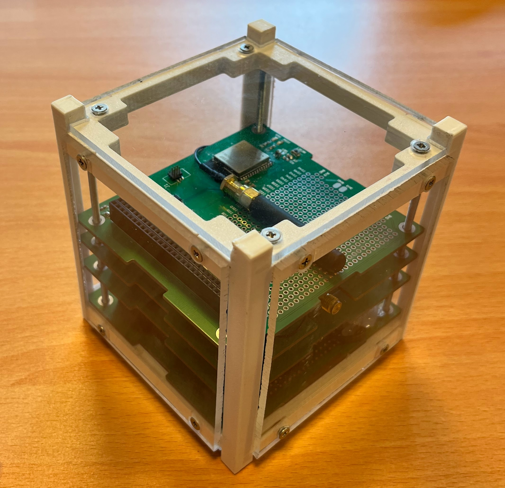
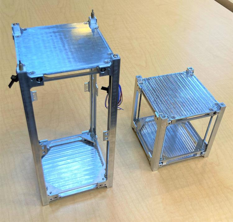
3D printable CubeSat mechanical Structure designed on Solidworks 2021. This mechanical structure follows the next standards:
The features of this design:
- 3D printable
- 90% of the unit available
- All the sides have screws to attach PCB’s
- It uses threaded rods to support the PCB’s subsystems. It improves structure strength.
The materials needed for the assembly are:
- 3D printed parts
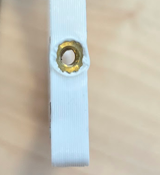
- 24pcs - M3 x 4 x 5 mm, M3 Thread Insert
- 24 - M3 Screws
- 4pcs - 90mm M3 Threaded rod
I need:
-
Printing Brass Nuts, M3. It could be bought from RS, or amazon.
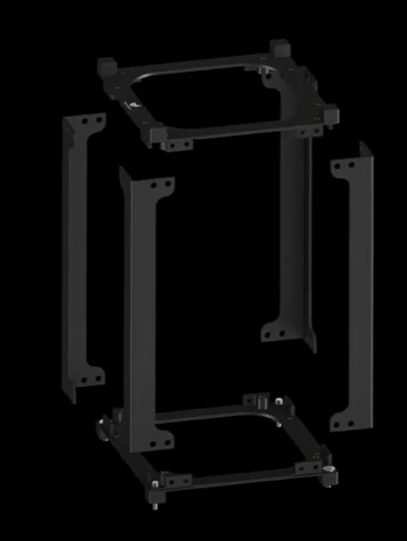
EnduroSAT

Problem about how to fix the PCB from top
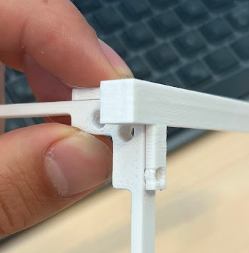
This solution, in which the threaded rod is secured from the side:
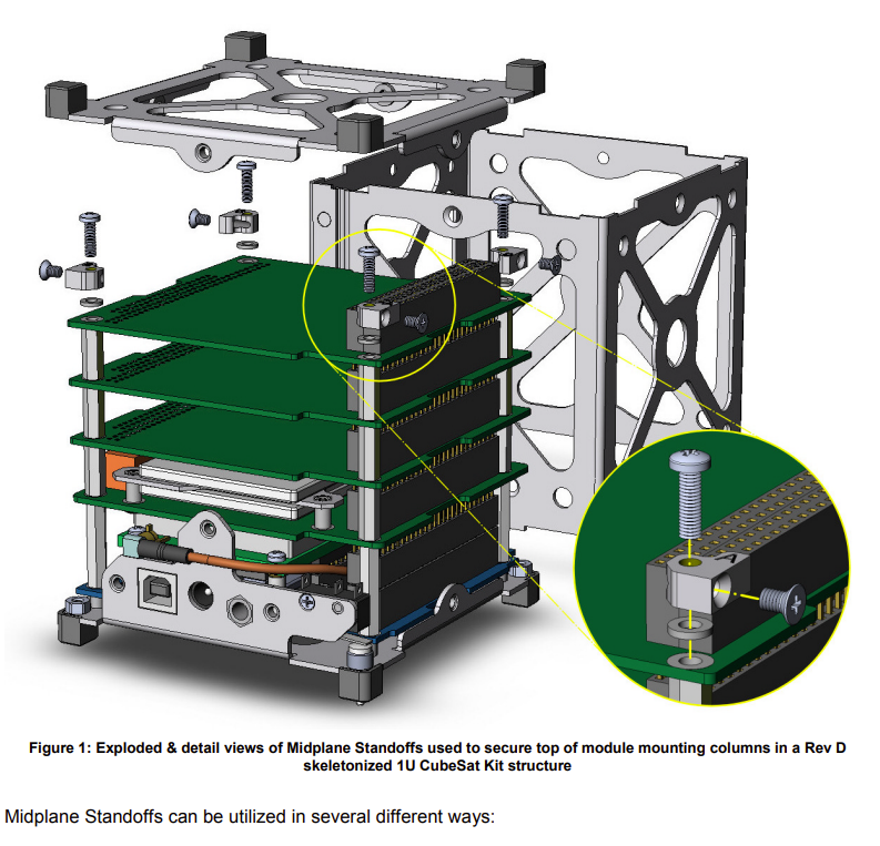
Or this solution in which is fixed from top and bottom with the threaded rod using a cover:

Problems first mechanical design
- The holes where I put the threaded heat inserts for 3d printing should be the diameter of the part. From the first print they are nice, but would be nice a bit more, maybe 0.46 mm
- Use 3 walls instead of 2
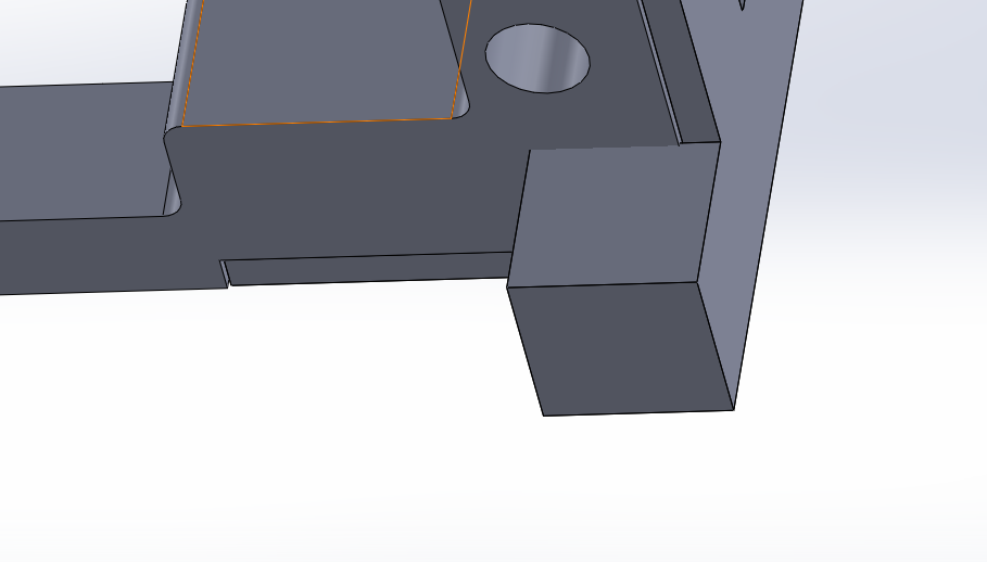
- That part needs to be higher, the structure is not very rigid. First picture DONE
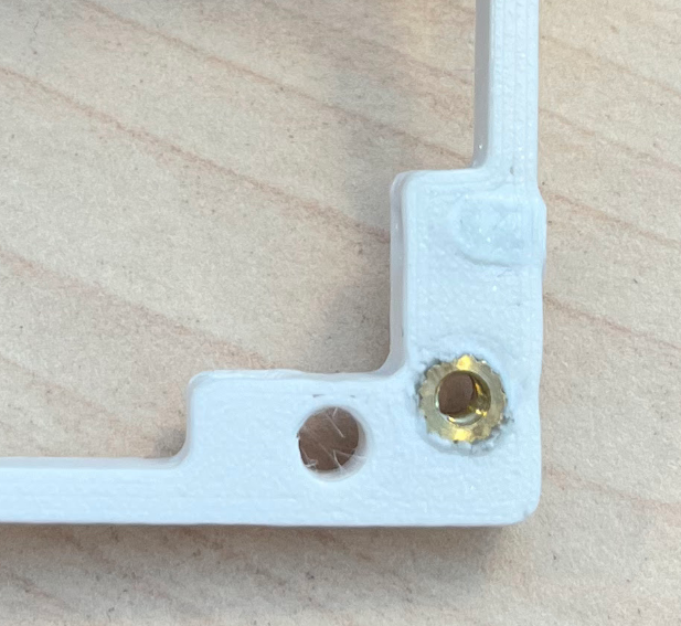
- There should be more spacing between the upper hole and the end of the part. Second picture. DONE
- In general the walls, in the thin part, needs to be thicker, the structure is weak. DONE
- I could integrate the first part on the second part, making it stronger. Let me explain more. The columns will stay the same, but the frame would go further, so the panels on the sides rest on the column and on the frame, not only on the column. DONE
- Apply purple loctite, that helps to not have vibrations.
- The pcb doesnt fit, check the measurements of the PCB. DONE
- Mark to show the orientation of the PCB DONE
- 3D printing tolerance from 0.1mm to 0.2mm, it is not enough.
- Something bad with tolerances