-
What I am specially interested is in how can students add software and access other resources of the CubeSat. How to add software/debug it easily.
-
Interesting approach of a big computer and the students send their commands there. It uses a linux computer with a Framework, that is being used by ESA. Basically is about packates that are transfered by CCSDS File Delivery Protocol (CFDP). It is based on the CCSDS Mission Operations concept.
-
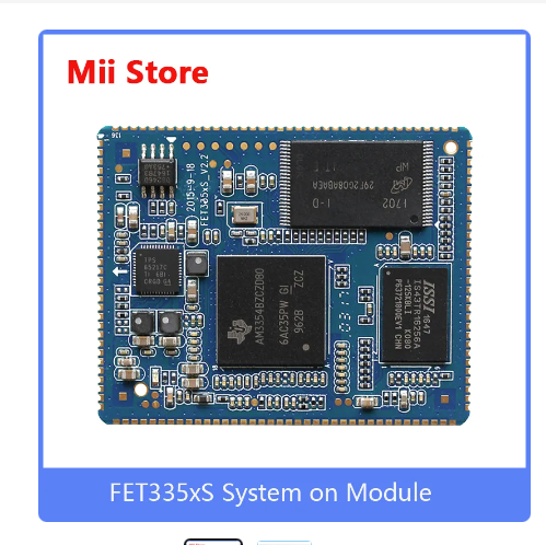
In the OPS-SAT it is used THIS compute module.
I have been thinking, and the SoC of DTUSAT is still a good approach that I have been using. The problem with the RISCV computer and those is that they are not very finished yet, and is necessary to implement the CAN bus by your own. If I am able to configure the can interface it would be different.
DISCLAIMER I have been trying to use the allwinner D1 on the mangopi and is giving me a lot of problems. Even when the cable is connected it losses IP. It seems that the hardware/software is not ready yet. For this reason I am going to use the pocketbeagle for my new designs.
Interesting CPU
I want to try the A335x Sitara processors because they suit for this application. The best ones are AM3352, AM3356, AM3357. In the datasheet there is a nice table comparing all of them. My favourite among those is the AM3356 because it can run with low CPU speed. Basically I want to base de design on the AM335x series, that I already have worked with, with a low frequency rate.
It would be super cool to design something like this:
Design A335x Reference
Next version
I am going to do a fast OBC version based on the pocket beagle. But the next version should be based on the TI AM623. I can use this System-On-Module, or this one, or even this one.
—
Fixing errors
20230915 I manufactured the OBC and it arrived. I soldered the connector, but the CAN interface doesnt work for now.
The next tasks to have a working OBC:
- Solder a new but with the connector correctly
- Check the PCB on the multimeter, osciloscope and note the errors
- Create the overlay
- Apply the overlay and test it
- Move the software of the old OBC to the new OBC
Known errors
- Some EPS are not working as expected. It is noisy.
- Some SD cards that are copied gives some errors when they boot.
- The OBC gives some errors on boot when the battery is depleated, you need to have it charged.
Creating a clean overlay
I created a overlay with the minimum stuff, removing all the hdmi, codecs, etc. It is called clean.dts. And the output of pins is like:
pin 32 (PB0): UNCLAIMED
pin 33 (PB1): UNCLAIMED
pin 34 (PB2): UNCLAIMED
pin 35 (PB3): UNCLAIMED
pin 36 (PB4): UNCLAIMED
pin 37 (PB5): UNCLAIMED
pin 38 (PB6): UNCLAIMED
pin 39 (PB7): UNCLAIMED
pin 40 (PB8): device 2500000.serial function uart0 group PB8
pin 41 (PB9): device 2500000.serial function uart0 group PB9
pin 42 (PB10): GPIO 2000000.pinctrl:42
pin 43 (PB11): GPIO 2000000.pinctrl:43
pin 44 (PB12): UNCLAIMED
pin 64 (PC0): UNCLAIMED
pin 65 (PC1): UNCLAIMED
pin 66 (PC2): device 4025000.spi function spi0 group PC2
pin 67 (PC3): device 4025000.spi function spi0 group PC3
pin 68 (PC4): device 4025000.spi function spi0 group PC4
pin 69 (PC5): device 4025000.spi function spi0 group PC5
pin 70 (PC6): device 4025000.spi function spi0 group PC6
pin 71 (PC7): device 4025000.spi function spi0 group PC7
pin 96 (PD0): UNCLAIMED
pin 97 (PD1): UNCLAIMED
pin 98 (PD2): UNCLAIMED
pin 99 (PD3): UNCLAIMED
pin 100 (PD4): UNCLAIMED
pin 101 (PD5): UNCLAIMED
pin 102 (PD6): UNCLAIMED
pin 103 (PD7): UNCLAIMED
pin 104 (PD8): UNCLAIMED
pin 105 (PD9): UNCLAIMED
pin 106 (PD10): UNCLAIMED
pin 107 (PD11): UNCLAIMED
pin 108 (PD12): UNCLAIMED
pin 109 (PD13): UNCLAIMED
pin 110 (PD14): UNCLAIMED
pin 111 (PD15): UNCLAIMED
pin 112 (PD16): UNCLAIMED
pin 113 (PD17): UNCLAIMED
pin 114 (PD18): UNCLAIMED
pin 115 (PD19): UNCLAIMED
pin 116 (PD20): GPIO 2000000.pinctrl:116
pin 117 (PD21): UNCLAIMED
pin 118 (PD22): UNCLAIMED
pin 128 (PE0): UNCLAIMED
pin 129 (PE1): UNCLAIMED
pin 130 (PE2): UNCLAIMED
pin 131 (PE3): UNCLAIMED
pin 132 (PE4): UNCLAIMED
pin 133 (PE5): UNCLAIMED
pin 134 (PE6): UNCLAIMED
pin 135 (PE7): UNCLAIMED
pin 136 (PE8): UNCLAIMED
pin 137 (PE9): UNCLAIMED
pin 138 (PE10): UNCLAIMED
pin 139 (PE11): UNCLAIMED
pin 140 (PE12): UNCLAIMED
pin 141 (PE13): UNCLAIMED
pin 142 (PE14): UNCLAIMED
pin 143 (PE15): UNCLAIMED
pin 144 (PE16): UNCLAIMED
pin 145 (PE17): UNCLAIMED
pin 160 (PF0): device 4020000.mmc function mmc0 group PF0
pin 161 (PF1): device 4020000.mmc function mmc0 group PF1
pin 162 (PF2): device 4020000.mmc function mmc0 group PF2
pin 163 (PF3): device 4020000.mmc function mmc0 group PF3
pin 164 (PF4): device 4020000.mmc function mmc0 group PF4
pin 165 (PF5): device 4020000.mmc function mmc0 group PF5
pin 166 (PF6): UNCLAIMED
pin 192 (PG0): device 4021000.mmc function mmc1 group PG0
pin 193 (PG1): device 4021000.mmc function mmc1 group PG1
pin 194 (PG2): device 4021000.mmc function mmc1 group PG2
pin 195 (PG3): device 4021000.mmc function mmc1 group PG3
pin 196 (PG4): device 4021000.mmc function mmc1 group PG4
pin 197 (PG5): device 4021000.mmc function mmc1 group PG5
pin 198 (PG6): device 2500400.serial function uart1 group PG6
pin 199 (PG7): device 2500400.serial function uart1 group PG7
pin 200 (PG8): device 2500400.serial function uart1 group PG8
pin 201 (PG9): device 2500400.serial function uart1 group PG9
pin 202 (PG10): UNCLAIMED
pin 203 (PG11): UNCLAIMED
pin 204 (PG12): GPIO 2000000.pinctrl:204
pin 205 (PG13): UNCLAIMED
pin 206 (PG14): UNCLAIMED
pin 207 (PG15): UNCLAIMED
pin 208 (PG16): UNCLAIMED
pin 209 (PG17): UNCLAIMED
pin 210 (PG18): UNCLAIMED
Creating clean overlay with CAN
I created the overlay, and.… it seems that the irq pin is not correctly configure, I am still debugging, but everything seems to be in place.
The problem is that the irq pin is not allocated. However it can be seen that is configure the bias pull up here root@ubuntu:/sys/kernel/debug/pinctrl/2000000.pinctrl# cat pinconf-pins
To know what is happening I am going to use the mangopi without anything connected and see if the pins are allocated.
Okey, I know what is happening, it seems that the SPI pins are not allocated. In the mangopi that should be working is like this:
pin 106 (PD10): device 4026000.spi function spi1 group PD10
pin 107 (PD11): device 4026000.spi function spi1 group PD11
pin 108 (PD12): device 4026000.spi function spi1 group PD12
pin 109 (PD13): device 4026000.spi function spi1 group PD13
pin 110 (PD14): device 4026000.spi function spi1 group PD14
pin 111 (PD15): device 4026000.spi function spi1 group PD15
pin 112 (PD16): device 2000c00.pwm function pwm group PD16
pin 113 (PD17): UNCLAIMED
pin 114 (PD18): device 2000c00.pwm function pwm group PD18
pin 115 (PD19): GPIO 2000000.pinctrl:115
pin 116 (PD20): GPIO 2000000.pinctrl:116
pin 117 (PD21): GPIO 2000000.pinctrl:117
pin 118 (PD22): device 2036000.spdif function spdif group PD22
and when is connected:
pin 106 (PD10): device 4026000.spi function spi1 group PD10
pin 107 (PD11): device 4026000.spi function spi1 group PD11
pin 108 (PD12): device 4026000.spi function spi1 group PD12
pin 109 (PD13): device 4026000.spi function spi1 group PD13
pin 110 (PD14): device 4026000.spi function spi1 group PD14
pin 111 (PD15): device 4026000.spi function spi1 group PD15
pin 112 (PD16): device 2000c00.pwm function pwm group PD16
pin 113 (PD17): device spi1.0 function irq group PD17
and the relevant is that the interrup looks like:
201: 11 sunxi_pio_level 81 Level spi1.0
And in the interrupts there is nothing, that is suppose is because there is nothing connected.
The next step is to check that the spi’s and the pins are configured as in the mangopi.
THE NEXT CODE IS IN A BOARD WITH THE LICHEE AND THE CAN INTERFACE SOLDERED:
pin 106 (PD10): device 4026000.spi function spi1 group PD10
pin 107 (PD11): device 4026000.spi function spi1 group PD11
pin 108 (PD12): device 4026000.spi function spi1 group PD12
pin 109 (PD13): device 4026000.spi function spi1 group PD13
pin 110 (PD14): device 4026000.spi function spi1 group PD14
pin 111 (PD15): device 4026000.spi function spi1 group PD15
pin 112 (PD16): UNCLAIMED
pin 113 (PD17): device spi1.0 function irq group PD17
However, it doesnt work when I try to turn on the interface.
I am a bit stuck. With the overlay I created CAN_clean is should be correctly, the SPI interface is up, and the irq is configured. However with the external spi it doesnt answer, and with the boards, there is one that doesnt answer to config and the other doesnt receive anything when the usb send can messages.
Is not working, so lets test with multimeter
In the board with the headers is not working when I put the external CAN mdoule. And that doesnt make sense, so I am going to see in the multimeter what is happening.
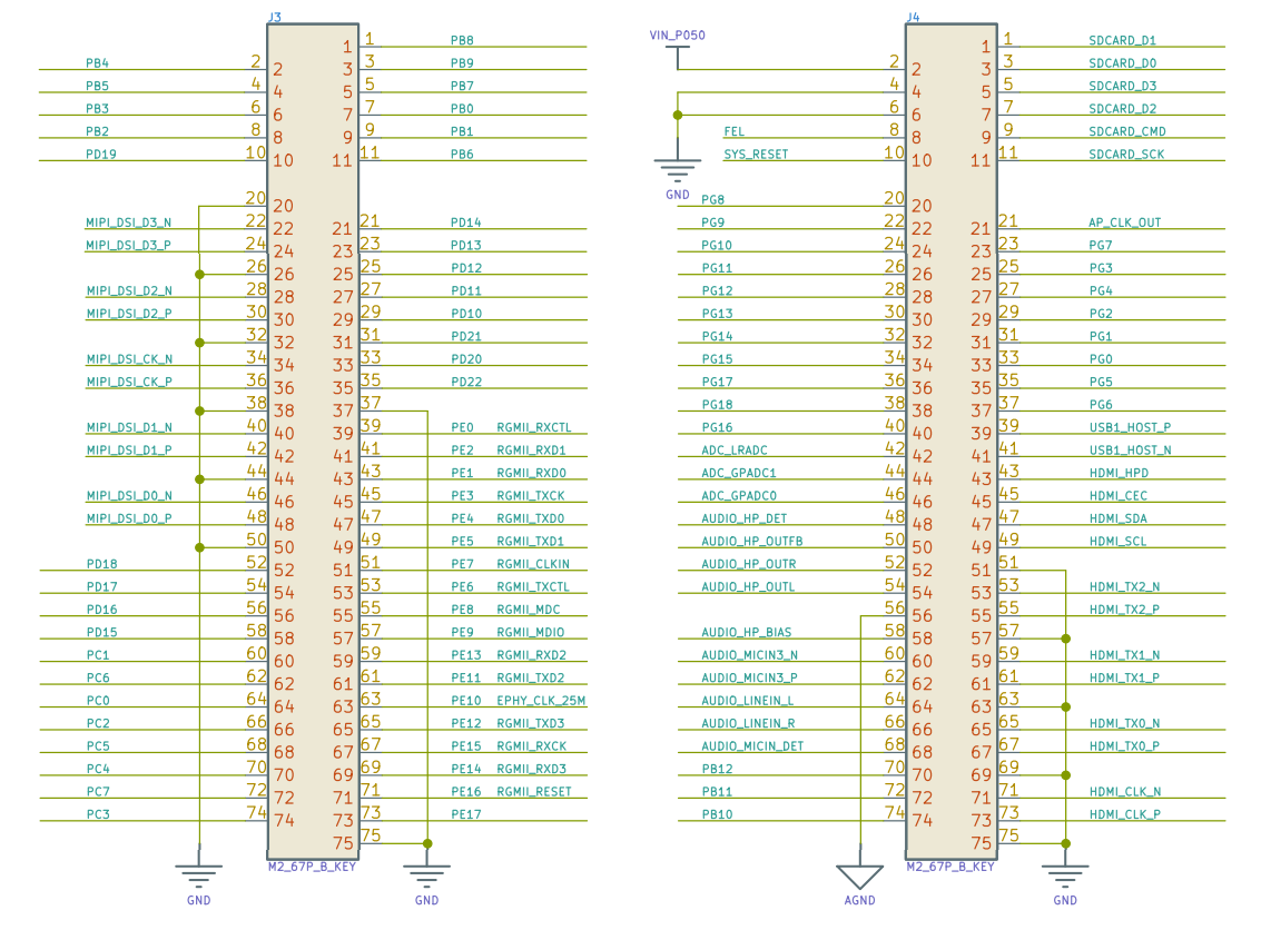
First the pinout of the board.

Working with external SPI
With the clean_can overlay is working when I put the external module of CAN. So is a hardware problem. I am going to check the schematic if there is something wrong.
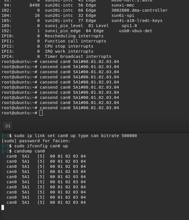
IS WORKING
The problem was the solderbridge is not connected correctly. The problem is that the line of GND was not on place. But is easy to fix, is just to remove the resistor and put the te RS of the can transceiver to GND. Basically is to solder everything of the Solderbridge.
Problems with OBC’s with copied software
I have noticed that the obc’s in which I have copied the code bit by bit there is a problem. I need to learn how to create an image correctly. Before I was doing with dd.
OBC very slow on startup
There are some services that makes the computer super slow to start:
- systemd-networkd-wait-online.service
- cloud-init.service
I am going to disable:
- cloud-init.service
- cloud-init-local.service
- cloud-final.service
- cloud-config.service