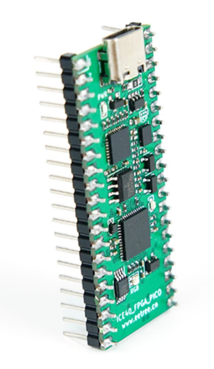
FPGA: ICE40UP5K SG48 Clock: 12 MHz
Getting started
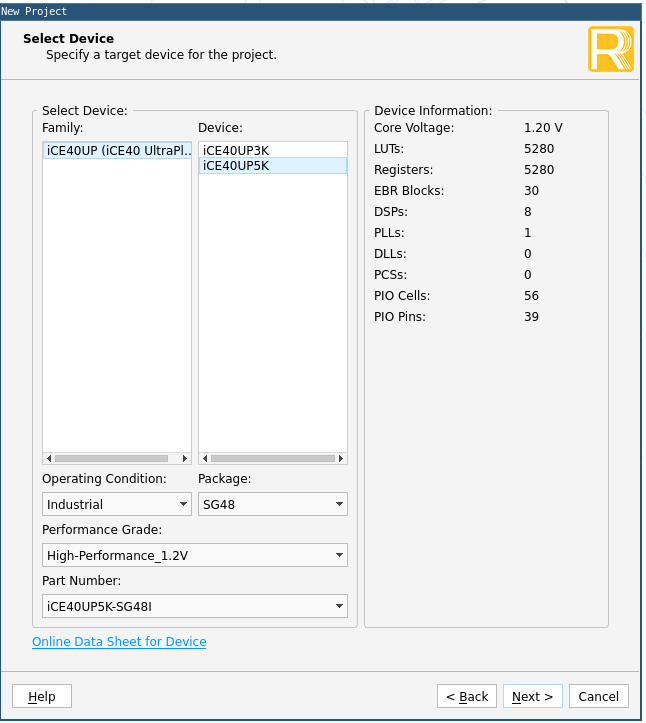
- Download Radiant
- Create a project
- Select Synplify Pro
- Create a VHDL file with the next code
library ieee;
use ieee.std_logic_1164.all;
use IEEE.NUMERIC_STD.ALL;

entity main is
  port (
    i_clock : in std_logic;
    o_led : out std_logic;
    i_button : in std_logic;
    o_otherled : out std_logic
  ) ;
end entity main;

architecture arch of main is

    constant CLOCK_FREQUENCY : integer := 12000000; -- input clock frequency (12 MHz)
    signal counter : unsigned(31 downto 0) := (others => '0'); -- 32-bit counter to measure 1 second
    signal r_led : std_logic := '0';
begin

    PROC_LIGHT : process( i_clock )
    begin
        if rising_edge(i_clock) then -- detect rising edge of input clock
                counter <= counter + 1; -- increment counter on each clock cycle
                if counter = to_unsigned(CLOCK_FREQUENCY, counter'length) then -- check if counter reaches 1 second
                    r_led <= not r_led; -- toggle the LED on and off
                    counter <= (others => '0'); -- reset the counter to start again
                end if;
            end if;
    end process ; -- PROC_LIGHT

  o_otherled <= i_button;
  o_led <= r_led;

end arch ; -- arch
- Synthesize Design
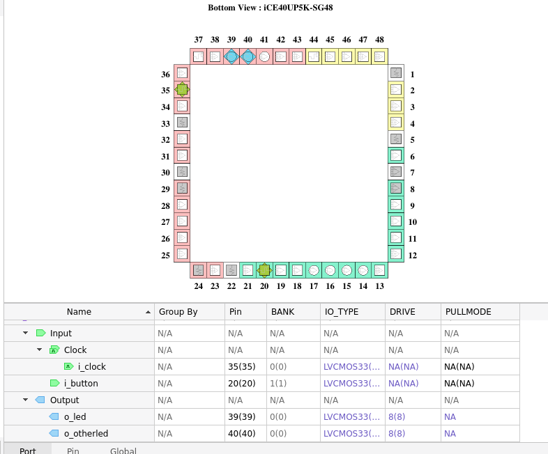
- Go to Tools > Device Constraint Editor and put the next constraints
- Then go to strategy1 > edit > Bitstream > Output Format > Raw Bit File ASCII
- Run Export Files
- Copy the exported
.rbtfile under impl1 into the STEPLink folder when you connect the fpga through USB
—
CONCLUSION
After a couple of days trying to upload some code I concluded that the board is not working as expected.