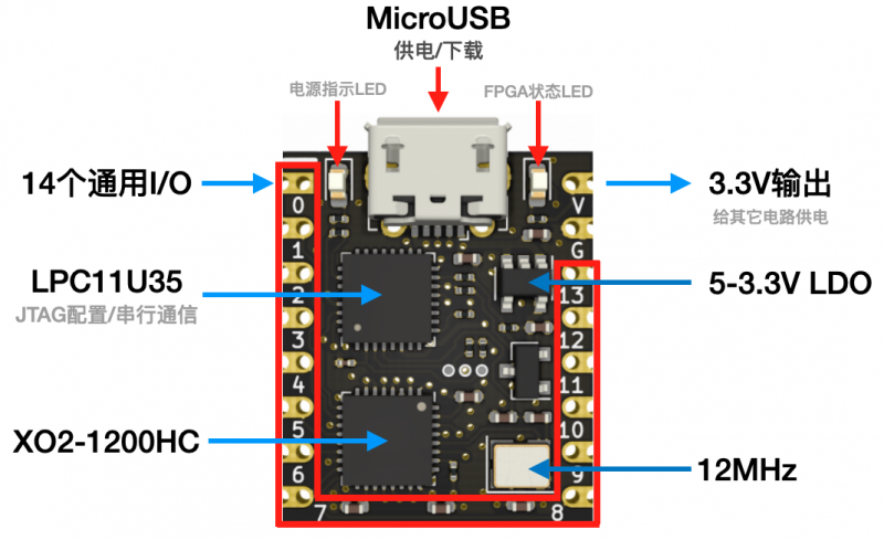
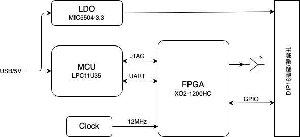
This FPGA can be found on aliexpress in a really small pcb. The documentation of this PCB can be fount on chiniese here. It is from the family of Lattice MachXO2 and it is needed Lattice Diamond in the free version to program them.
How to upload your first program to the FPGA
- To install Lattice Diamond use this docker on github, it works perfectly. And when generating the license use “ Request Node-locked License”.
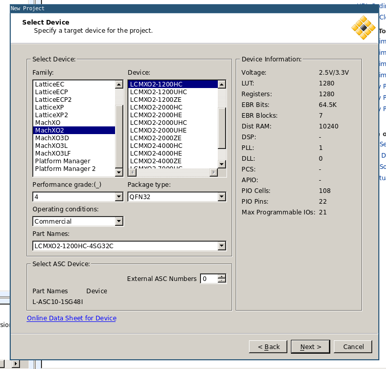
- Create a new project and select the next parameters
- Add the following source code:
library ieee;
use ieee.std_logic_1164.all;
use IEEE.NUMERIC_STD.ALL;

entity main is
  port (
    i_clock : in std_logic;
    o_led : out std_logic;
    i_button : in std_logic;
    o_otherled : out std_logic
  ) ;
end entity main;

architecture arch of main is

    constant CLOCK_FREQUENCY : integer := 12000000; -- input clock frequency (12 MHz)
    signal counter : unsigned(31 downto 0) := (others => '0'); -- 32-bit counter to measure 1 second
    signal r_led : std_logic := '0';
begin

    PROC_LIGHT : process( i_clock )
    begin
        if rising_edge(i_clock) then -- detect rising edge of input clock
                counter <= counter + 1; -- increment counter on each clock cycle
                if counter = to_unsigned(CLOCK_FREQUENCY, counter'length) then -- check if counter reaches 1 second
                    r_led <= not r_led; -- toggle the LED on and off
                    counter <= (others => '0'); -- reset the counter to start again
                end if;
            end if;
    end process ; -- PROC_LIGHT

  o_otherled <= i_button;
  o_led <= r_led;

end arch ; -- arch
- Go to process > Synthesize Design > Run, select VHDL and Map trace
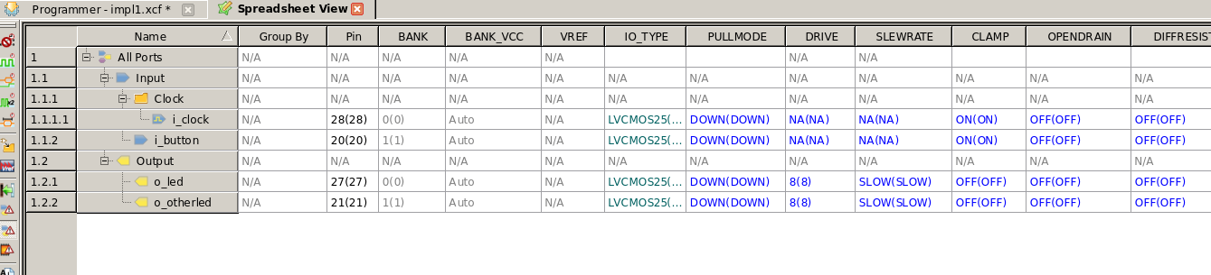
- Then Tools > Spreadsheet view
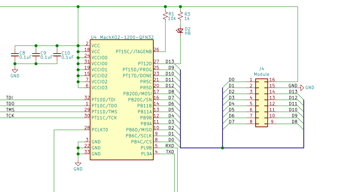
- Set the pin numbers using the schematic. The clock is on pin 28
- Then run P&R
- On export files select JEDEC file, and ignore the error of the clocks.
- Take the jed file and place it on the usb drive that the board created.
In order to select the pin numbers go to Tools > Spreadsheet view. There is Pin assignment and Port assignment.