- Docs
- Document explaning the SEL circuit
- Design document
- Previous work and inspiration of the new board
SSCB is the subsystem carrier board.
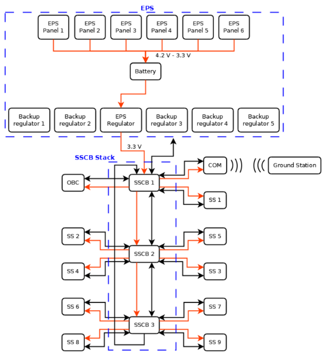
The functions of the SSCB:
-
Connect multiple subsystems, and multiple SSCB’s
-
It has a select circuit in which you can select which subsystem you want to debug, program and power on. It is controlled with the resistors.
-
Some voltages regulators.
-
SSCBs are daisy chained together with an FX23 connector from Hirose.
-
The latest version is on branch SSCB_Updating, both in the dtusat and the dtusat-common (kicad components library)
The SSCB:
- An old version had a FPGA
- there is a debugger interface. SWD programmer
- 2 pins, subsystem select to multplex the signal.
- The multiplex is placed wrong, it is necessary to rotate 180º
- I need to check the interface of the SSCB, Denis doesnt know exactly the interface with the programmer.
- Maybe, hub with 4 ports to program, and then another as a dubugger.
- Benjamin was the last student working on the SSCB. I received a mail with known boards.
- The USB type c is connected to a breackout board, with a programmer and a small microcontroller with the system selection
- In the Lora subsystem, it was developed with arduino but then Denis changed to LPC. MCU Xpresso to program it, there are some supported libraries for the interfaces of the microcontroller.
- Denis was the cosupervisor of the project. It is basically a beagle bone, a bb image should powered on, it is necessary to change the device tree.
- The usb and the OBC, should mount a network interface on USB, and I should be able to connect via ssh. Denis recomends me to take a breakout board and connect power suppies, SWD programmer and start from that.
- The breakout board that I have has a problem and it is easy to confuse with the direction. A new breakout board, smarter, was developed but denis dont remember where.
- PI network with Saturn PCB Design. Then put a comment “Zdiff=100 Ohm on this traces”. There is another software to get the values of the pi filters, SimSmith.
- PCBExpert software to generate footprints.
- I put a transceiver:
- Get the input impedance of the transceiver from the datasheet. In the frequency of operation.
- If the pin is 50 ohms and the connector is 50 ohms, check in jlcpcb how to get 50 ohms and put in the comments that you want 50 ohms.
- If the connector is 100 ohm, put a pi filter, get the values with the software simsmith, and then ask jlcpcb to adjust the 50 ohms at the trace after the filter.
The interface of 40 pins:
- The TBD are used in the OBC.
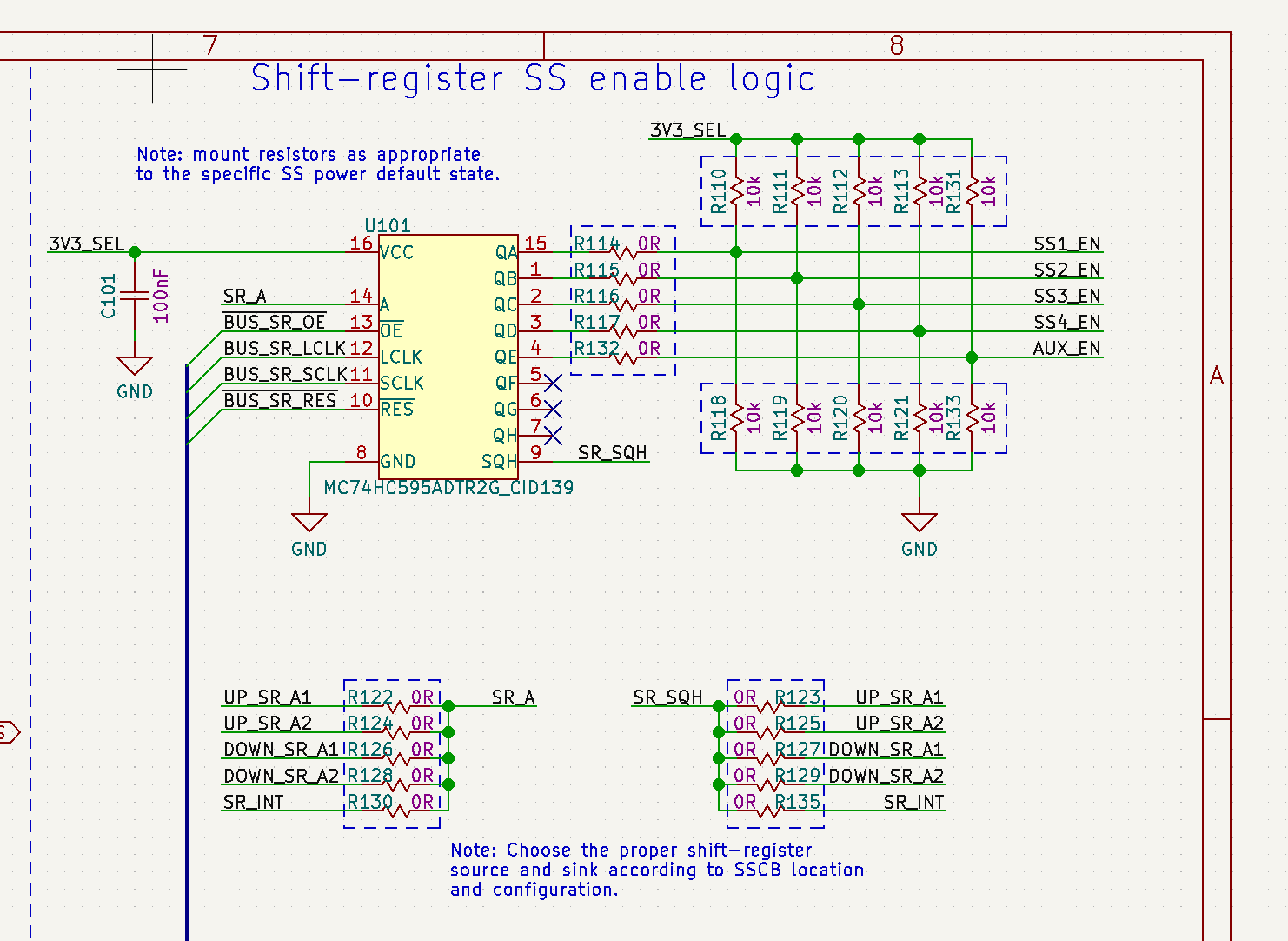
- The SR are used on a shift register, that controls the power of the different subsystems.
- MALE and FEMALE, convencion, female connector gives power, that is the decision.
Prototol in te communications:
-
A lot of discussion on the topic: Gomspace (SCP) made a protocol, also CCSDS was used. Denis used scp in the packet. SCP defines a framework between subsystems, there is no master. They did a project with GOMspace, and the communication was with SCP. The should be happy to help.
-
The resistors are to configure the board, the resistors should be desoldered.
-
4 Latchup op amps.
-
FTDI, there is a UART interface. Probably not used as a programmer.
-
FX23 connector to stack more boards. DF17
-
LPCLink debugger at CIF, René remember a wrong version of the board in the CIF.
—
Update 16 Feb 2023
I fixed the placement of the multiplexers and put the opamp. I have been looking into the resistors of the SR and I decided that I am going to remove all of them because in the best scenario I am going to use only 2 ss and none of them are accessing the SR. Not sure how it works, but my conclusion is that this SR is used to interconnect more than one SSCB but only one is coordinating the info of the SR. I am removing all the resistors in that photo.
Update 17 Feb 2023
Today I want to see if the board is working and see if I am able to program the microcontroller.
Some questions:
- What is connected to the USB-C?

The USB type C is following a strange pinout that is not compatible with usb type C. It can be used a cable USB2 to usb C.
- Whare is the power? Why nothing is connected to RAW3.3V
- This board is designed to be connected to the EPS, that should be in J1 or J2. A temporal fix is to directly put a jumper between the raw3v3 in j1 to the DBG_3V3
I dont understand the circuit of SEL. It seems that 3V3_SEL is not working.
Update 20 Feb 2023
This circuit is used to activate and deactivate the different subsystems. The SEL4 schematic in the project is used to power the 3V3_Sel signal that is used for the shift register.
- What is CURR-?
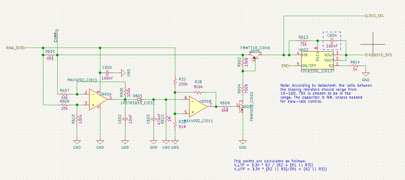
I am not able to undestand that circuit, I guess is a latchup depending on the voltage drop. But there is not documentation / simulation.
—
Update 21 Feb Meeting
SEL:
- Single Event Latch up: It shut down when it exceed 700 mAh. The equation in the schematic is wrong.
- At the beginning is not working because I need to put a load.
- Shift register, the OBC generates the signal to power on or off the different SS. If you put the top resistors row is always connected, if you put left resistors is controlled by the OBC, if you put the resistors at the botton it is powered off.