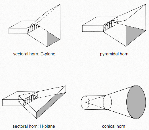
Coordinate system
The \(\vec z\) direction is pointing outside of the horn in the direction of radiation. The \(\vec x\) and \(\vec y\) and placed using the rule of the right hand, the \(\vec x)\ is located in the longest side of the aperture. The E field is located in the plane YZ, and the H plane is located in the XZ plane. So the E-plane will always have the shortest side (b), and the H-plane will have the longest side (a).
Sectorial horn antenna are more directive in the plane in which is more opened.
To improve the directivity and radiation efficiency, the waveguide should have an extended aperture to reduce the abrupt change from waveguide to open space.
- The task of the horn is to provide a gradual change so that most (all) of the forward propagating energy is radiated into the open space.
- The horn can be considered as a matching device between waveguide and open space
- Flaring of the waveguide is done to
- increase directivity (narrower beam width)
- provide impedance match
- improve radiation efficiency
Pyramidal horn geometry
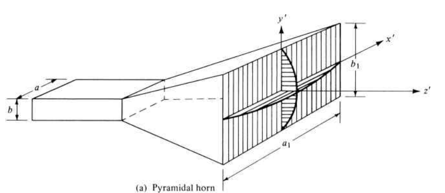
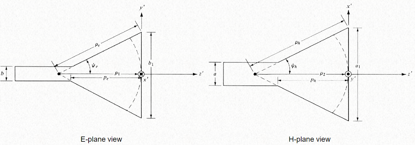
Where the point is the virtual apex.
In order to be a pyramidal horn antenna it mush satisfy:
$$ p_e = (b_1 - b) \Big [ \Big ( \frac{\rho_e}{b_1} \Big )^2 - \frac{1}{4} \Big ]^{1/2} \\ p_h = (a_1 - a) \Big [ \big ( \frac{\rho_h}{a_1} \Big )^2 - \frac{1}{4} \Big ]^{1/2} $$
Aperture field
The horn antenna is treated like an aperture antenna.
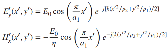
𝐸𝑧 and 𝐻𝑧 are non-zero (especially at the aperture edge), because the field is fringing/binding at the aperture.
Far field approximation
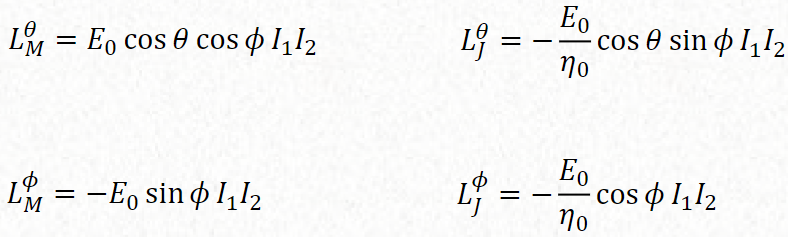
The aperture far field approximation:

Where the Lj and Lm are:
In a horn antenna it is possible to have maximum off axis, this is the maximum radiation is not towards the antenna. This is possible when the phase error taper at the aperture is such that the rays emanating from the different parts of the aperture toward the axis are not in phase and do not add constructively.
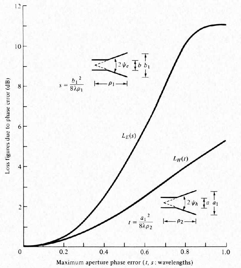
The optimum aperture is, that comes from the phase error over aperture:
$$ b_{1,optimum} \approx \sqrt{2 \lambda_0 \rho_1} \\ a_{1,optimum} \approx \sqrt{3 \lambda_0 \rho_2} $$
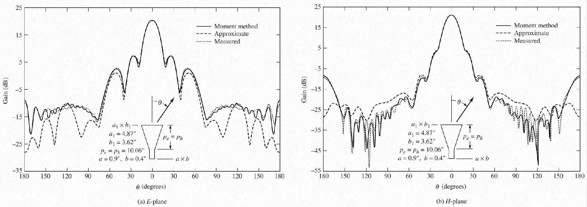
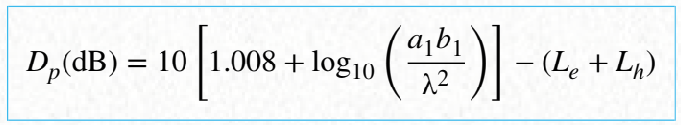
Approximation of the directivity
Conical horn
It happen in the mode TE11. This horn antennas are better for circular polarisation.
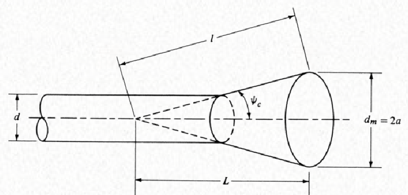
Optimum diameter:
$$ d_{m,optimum} \approx \sqrt{3 \lambda_0 l} $$
Becase of the order mode TE11 the directivity is not the same for E and H plane, that is why it is necessary to use a corrugated horn. It is more directive in E plane:
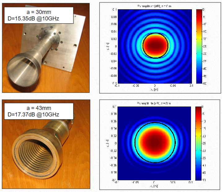
A corrugated antenna reduce the cross polarisation, and improve the radiation efficienty (from 50% to 75%). However it increses the SWR of the antenna.
The effect of the corrugations on the walls of a horn is to modify the electric field distribution in the E-plane from uniform (at the waveguide-horn junction) to cosine (at the aperture). Through measurements, it has been shown that the transition from uniform to cosine distribution takes place almost at the onset of the corrugations
Aperture-matched horn
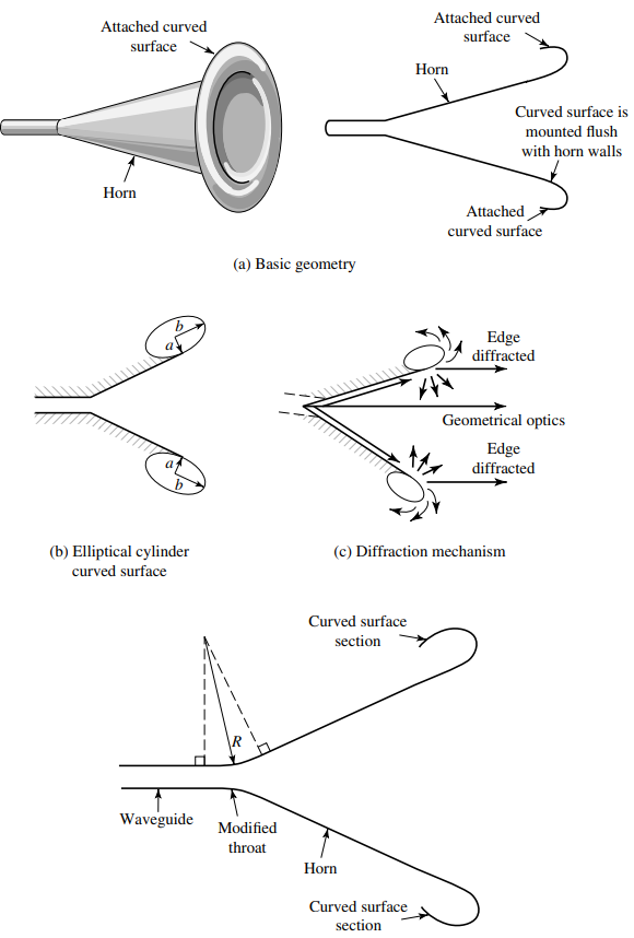
The introduction of the curved sections at the edges does not eliminate diffractions; instead it substitutes edge diffractions by curved-surface diffractions which have a tendency to provide an essentially undisturbed energy flow across the junction, around the curved surface, and into free-space.
Compared with conventional horns, this radiation mechanism leads to smoother patterns with greatly reduced black lobes and negligible reflections back into the horn.