Coordinate system
The \(\vec z\) direction is pointing outside of the horn in the direction of radiation. The \(\vec x\) and \(\vec y\) and placed using the rule of the right hand, the \(\vec x\) is located in the longest side of the aperture. The E field is located in the plane YZ, and the H plane is located in the XZ plane. So the E-plane will always have the shortest side (b), and the H-plane will have the longest side (a).
Radiation integrals
Electrical far-field condition: electrical distance: \(k_0 \lvert \vec r \lvert » 1\)
Geometrical far-field condition based on antenna size: \(\lvert \vec r \lvert > \frac{2 D^2}{\lambda_0}\)
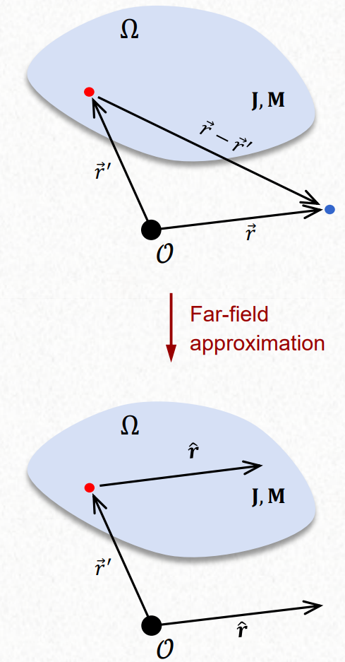
Given the J and M inside a region, electrical current density and magnetic current density, we can use the Helmholtz equation and Green function to get the A and F, magnetic vector potential and electric vector potential. From A and F we can use Lorenz gauge to get E and H. This E and H is valid when the observer is sufficiently far away.
Radiation integrals from Helmholtz equatoin and Green function:
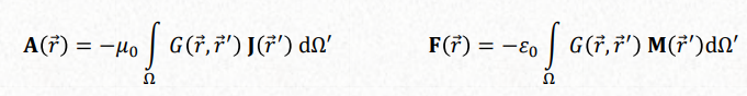
Lorenz gauge:

All the equations would be, with the solution:
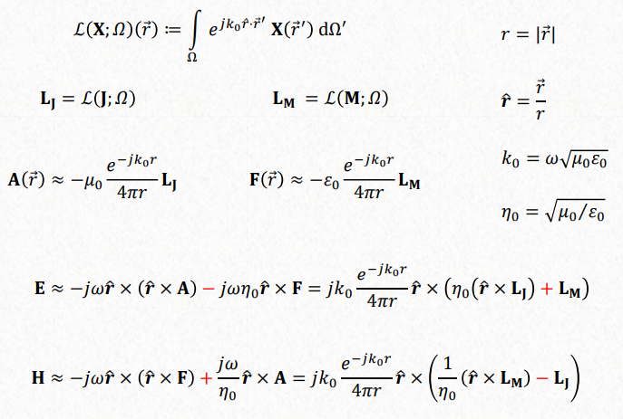
In spherical coordinates would be:

Huygens’, Love’s and Schelkunoff’s equivalence principles
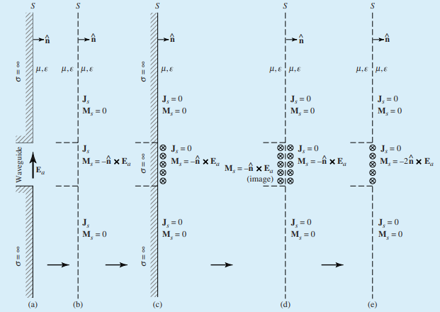
- b. Huygens’ equivalence principale equivalent surface current densities in surface S. Boundary conditions.
- c. Love’s equivalence principal. Set the internal fields to zero. Use the Schelkunoff’s equivalence principle, the space ocuppied inside the region can be filled with any medium, use a PEC.
- d. Apply the image techniques and remove the PEC. The image current of a tangential (horizontal) magnetic current over a PEC surface is identical to the original current.
- e. Define the equivalent current only over the aperture of the horn antenna. This approximation is in general very good in the direction of the main beam but less accurate towards the sides.
Rectangular aperture
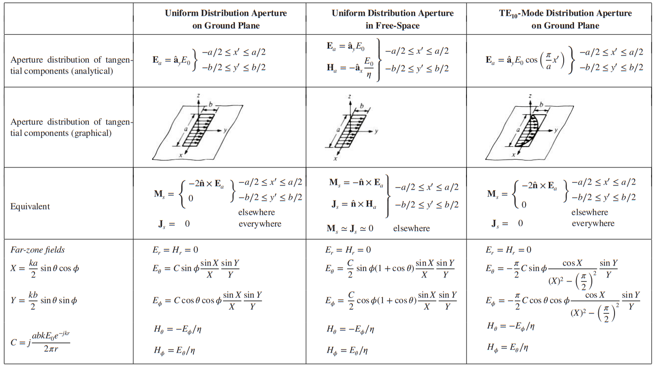
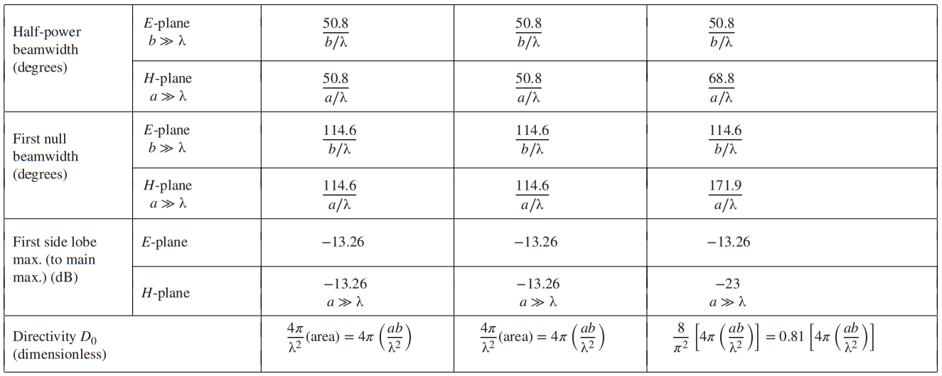
$$ FNBW \Rightarrow \frac{k_0 w}{2} \cdot \sin{\theta_n} = n \pi \\ HPBW \Rightarrow \frac{k_0 w}{2} \cdot \sin{\theta_n} = 1,391 \\ \text{Number of lobes} = 2 N -1 \rightarrow N \le \frac{w}{\lambda} \\ w = [a, b] D = 4 \pi \frac{a \cdot b}{\lambda^2} $$
Cilindrical aperture
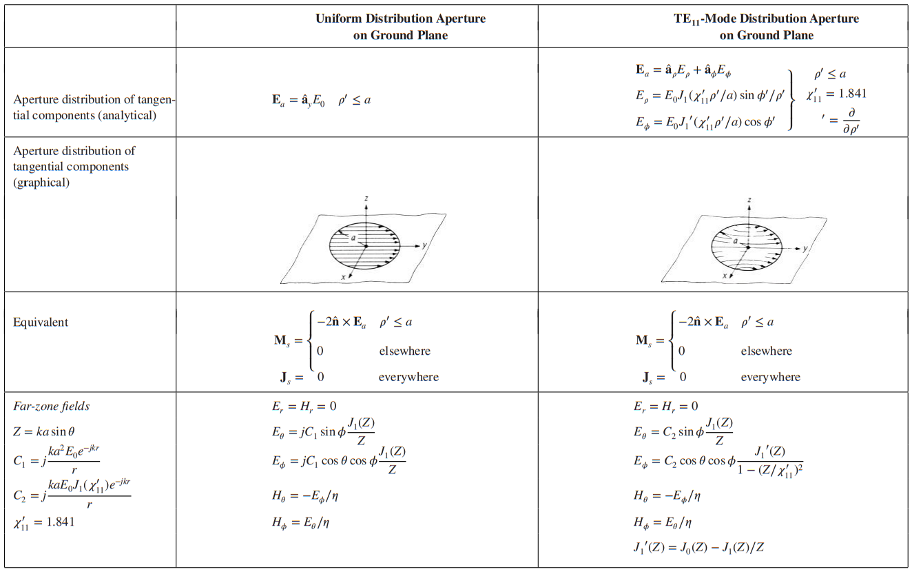
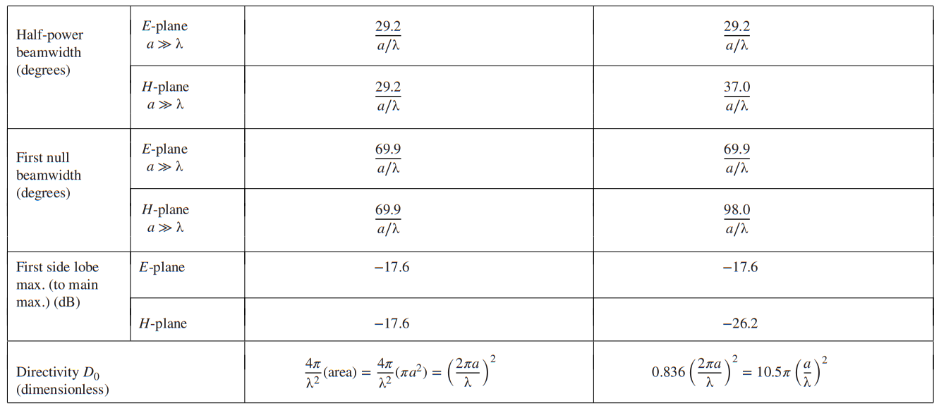
Directivity is proportional to the electrical area, beamwidth is inverse proportional to electrical height/width/radius, side lobe level decreases with increasing amplitude taper in the aperture, number of sidelobes increases by increasing amplitude taper in the aperture.
Babinet’s principle
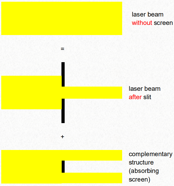
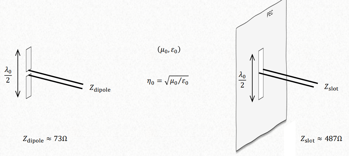
Babinet is for optics, does not consider the polarization. That is why we use booked extended babine’ts principle to polarized fields. Booker’s principle can be used to obtain the terminal impedances of a complementary structure, provided the terminal impedance of the original one is known. To get the impedance of an apperture when we know the impedance of the complementary structure.
$$
Z_s \cdot Z_c = \frac{\eta^2}{4}
$$
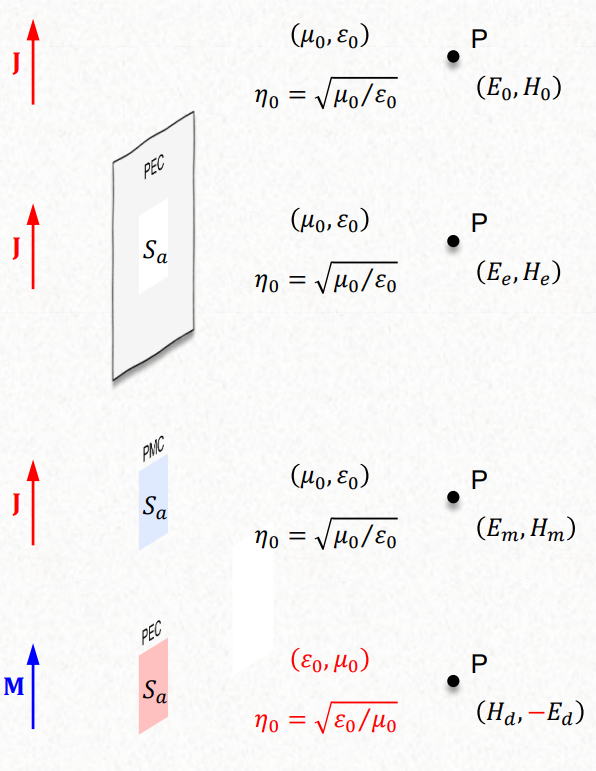
$$ (E_0, H_0) = (E_e, H_e) + (E_m, H_m) $$
Fourier-transform analysis of aperture antennas
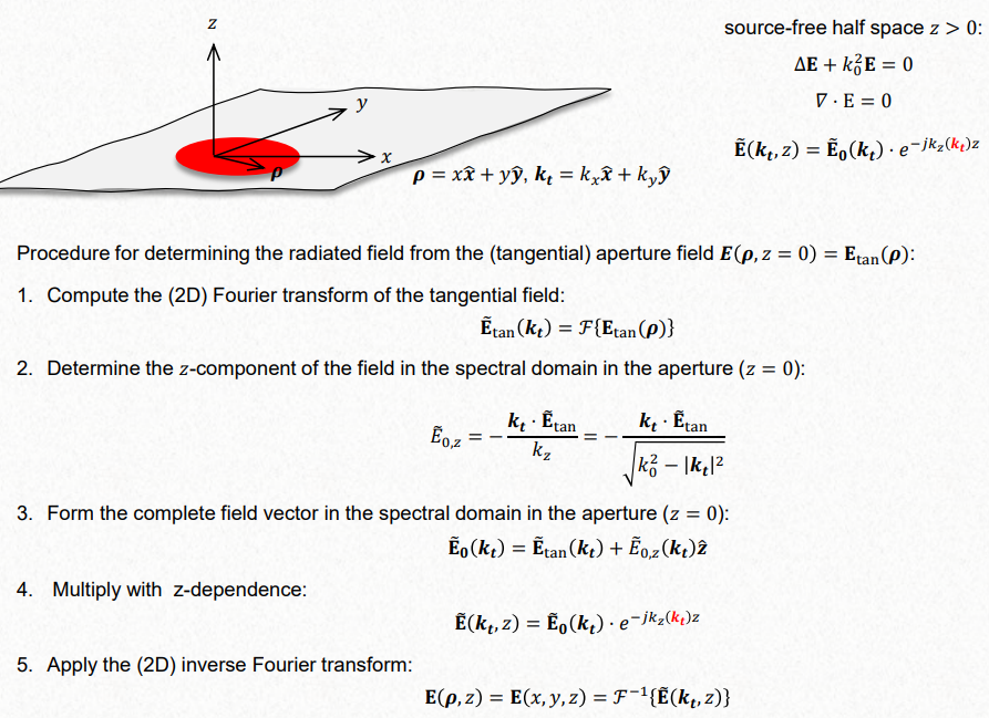
The fourer transform of a aperture is a sinc. It is a easier approad. That is why in TE10 the field H plane is bigger, because of the fourier transform of a pulse with a half sine.