Quiero diseñar una antena para 1.6 GHz. Frequencias del elektroL3
Frequencia: 1.692 GHz
En el libro de Practical Antenna Handbook en torno a la página 417 habla de antenas de microondas. Por aquí pondré algunas cosas importantes.
Cojo del libro algunas cosas:
A circular waveguide feed produces optimum illumination, and rectangular waveguides are less than optimum
Lo suyo sería que el feed sea un Horn antenna radiator. Dentro debería de ser de la siguiente forma:
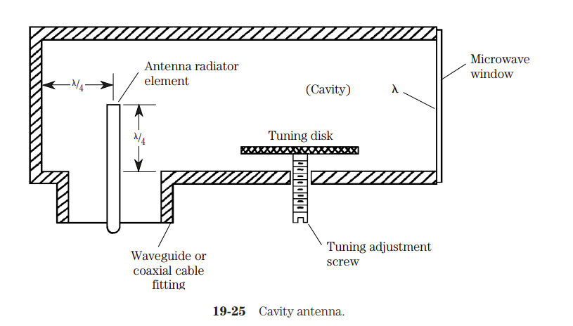
Vale, creo que para la antena del ELEKTRO voy a hacer una horn antenna radiator con una cavity antenna y hecho para la distancia de nuestra antena.
Las ecuaciones del horn son las siguientes:
$$ G = \frac{10 A}{\lambda^2} $$
Where:
- A is the flange of the antenna
- \(\lambda\) is the wavelength in the same units
The -3-dB beamwidth for vertical and horizontal extents can be approximated from:
$$ \Phi_{v} = \frac{51 \lambda}{b} \quad degress \\ \Phi_{h} = \frac{70 \lambda}{a} \quad degress $$ where
- \(\Phi_v\) is the vertical beamwidth, in degrees
- (\Phi_h\) is the horizontal beamwidth, in degrees
- a, b are dimensions of the flared flange
- \(\lambda\) is the wavelength
Un pdf bastante amable con algunas ecuaciones que definen a los feed horns.
Un documento de la ARRL que construyen un circular horn con las fórmulas
Low cutoff frequency of a waveguide
Below this frequency the waveguide does not operate.
The low cutoff frequency of a rectangular waveguide:
$$ f_c = \frac{c}{2a} \\ \lambda_c = 2 \cdot a $$
In which a is the wide waveguide dimension.
The low cutoff frequency of a circular waveguide:
$$ f_c = \frac{1.8412 c}{2 \pi r} \\ \lambda_c = 3.412 \cdot r $$
In which r is the radious of the waveguide.
Circular waveguide - Practical Antenna Handbook
$$ f_{cutoff} = \frac{175.698}{d_{mm}} \\ G = \frac{k (\pi D)^2}{\lambda^2} \\ BW = \frac{70 \lambda}{D} \ degrees \\ F = \frac{D^2}{16d} $$
In which:
- \(f_{cutoff}\) is the cutoff frequency
- \(d\) is the cutoff frequency
- \(G\) is the gain over isotropic
- \(D\) is the diameter of the reflector
- \(BW\) is the beamwidth, the half power beam width. The full beam width should be the double of the BW
- \(F\) is the focal length
- \(\lambda\) is the wavelength
- \(k\) is the reflector efficiency (0.4 to 0.7, with 0.55 being most common)
Circular waveguide horn antenna - ARRL
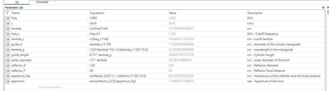
$$ f_c = \frac{1.8412 c}{2 \pi r} \\ \lambda_c = 3.412 \cdot r = 1.706 \cdot d \\ \lambda_g = \frac{\lambda_0}{\sqrt{1 - \big ( \frac{f_c}{f}^2 \big )}} = \frac{1}{\sqrt{\frac{1}{\lambda^2} - \frac{1}{\lambda_c^2}}} \\ \text{Cylinder length} = 0.75 \cdot \lambda_g \quad \text{Assumption} \\ \text{Outer diameter} = 1.5 \cdot \lambda \\ \text{Outer length} = \frac{outer_{diameter} - guide_d}{2 \cdot sin(apperture)} \\ \text{Aperture} = atan(\frac{outer_{diameter}/2}{outer_{length}}) $$
In which:
- \(lambda_c\) is the cutoff lambda
- \(r\) is the radious of the circular waveguide
- \(d\) is diameter of the circular waveguide
- \(f_c\) is the cutoff frequency of the circular waveguide
- \(\lambda_g\) is the wavelength in the waveguide
- \(f\) is the frequnecy
- \(lambda\) is the wavelength in free space
A screenshot from CST with the formulas:
Different results
I have made the “final” design, but I want to modify some variables and watch what happen. The parameters that I want to change are:
- outer_length -> Make it smaller
- guide_length -> Make it smaller
- outer_diameter -> Make it smaller
Base results
Frequency -> 1.692 GHz
- Main lobe: 12.8 dBi
- Angular width (3dB) Phi = 90: 38.5
Guide-length smaller
- No change, only angular width = 38.9
outer_diameter smaller
Less directive
outer_length smaller
Less directive
Cantenna - Muy poco directiva
Hace que la antena pase a ser muy poco directiva.
Conclusion
The most consistent results are those showed in the arrl article. Changing some parameters does not make a big improvement. The unique improvement in the base antenna proposed in the ARRL article is that the waveguide can be 0.25 * lambda_c, and there is no big change.